
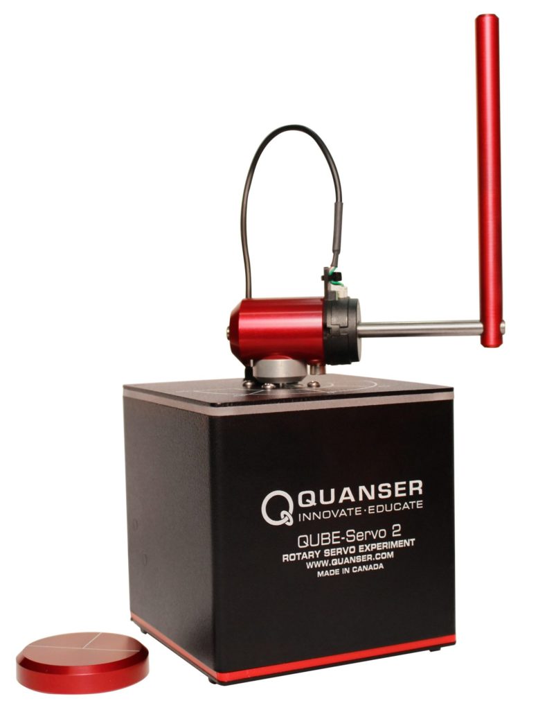
Since its initial release 7 years ago, our QUBE-Servo 2 has been widely adopted by universities across the world. It is supplied with two interchangeable modules, an inertia disc and a pendulum, which can be used to conduct a series of standard control experiments. But one of the key features of the QUBE is its flexibility, since you can build and attach your own modules. In this blog I am going to show how instructors can take advantage of this feature to setup a unique design-based learning approach for their course, lab, or project that can be tailored to different levels of students.
Project Overview
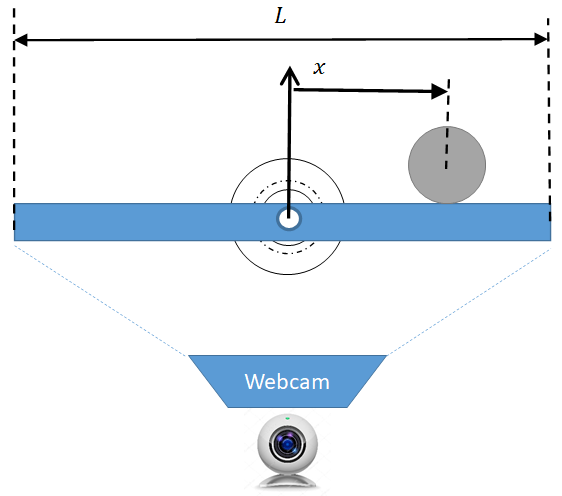
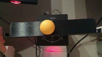
To demonstrate the idea, we decided to develop a classic ball and beam project for the QUBE-Servo 2. From a controls perspective, controlling the ball on a beam using a servo poses a unique set of challenges, which I have discussed in an earlier blog post. This project allows students to design their own beam and implement a vision-based ball and beam control using a webcam. A schematic drawing as well as an actual prototype are shown below. The system I designed consists of a 3D printed L-shaped beam that directly mounts onto the DC motor hub and a standard ping-pong ball. However, different types of beams and balls could be used.
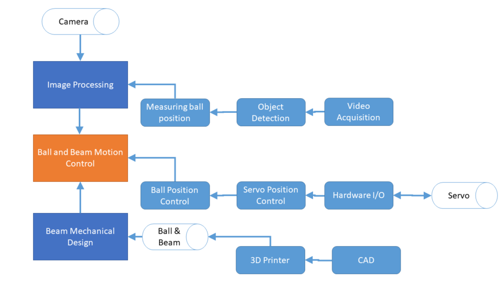
A high-level view of the various tasks involved in this project are illustrated below. It consists of mechanical design of the beam assembly, implementing a control scheme for balancing the ball, as well as image processing.
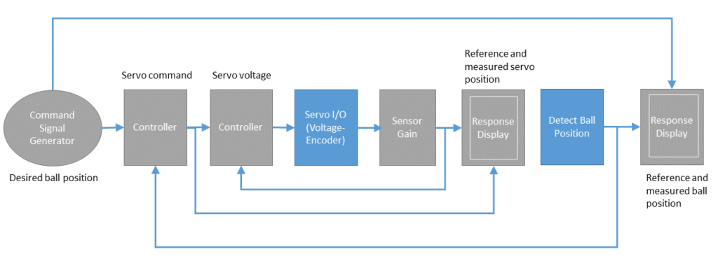
The ball and beam control loop concept is shown below. The position of the ball is measured using a webcam and various image acquisition and processing software tools (e.g. QUARC Video Capture block). The outer loop, the ball position controller, computes the servo angle needed to stabilize the ball at the desired ball position based on the measured ball position. The inner loop, the servo position controller, applies the voltage needed to track the desired servo angle based on the current angle measured by the encoder.
Below is a video of our prototype in action.
Modern Mechatronic System Design Approach
A mechatronic system is a type of smart system that integrates sensors, actuators, computational abilities, and communication protocols. A drone, for example, is a mechatronic system. It has an on-board processor with an IMU sensor, and propeller actuators.
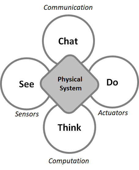
Based on the above definition, our proposed ball and beam system is also a mechatronic system, as it incorporates the following components:
- Sensors: QUBE-Servo 2 encoder and ball position sensor (e.g. webcam)
- Actuators: QUBE-Servo 2 DC motor
- Computation: Controller running on PC/laptop/MCU
- Communication: QUBE-Servo 2 USB data-acquisition (DAQ) device
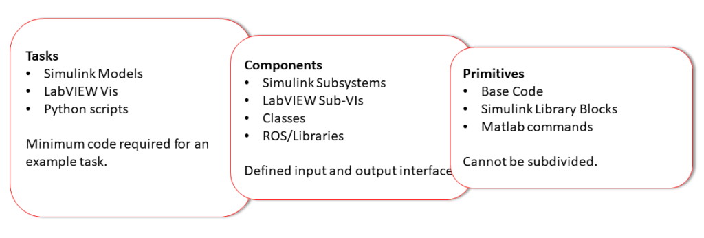
The software resources required to accomplish the project may be divided into the three groups shown below: tasks, components, and primitives.
In order to cater to different experience levels (i.e. undergraduate and graduate), the instructor can choose what to supply. Here is a sample breakdown:
| Level 1 | 1st or 2nd year undergraduate |
|
| Level 2 | 3rd or 4th year undergraduate |
|
| Level 3 | Graduate or advanced undergraduate project |
|
For example, if this project is implemented using MATLAB/Simulink and QUARC, depending on the intended level, students may do the following:
- Level 1: Full Simulink model (i.e. task) is supplied. Student would test the model and tune values. No major design modifications to be done.
- Level 2: Instructor supplied Simulink library that includes software subsystem (i.e. components). Students use the pre-defined Simulink subsystem block in those libraries to design the task.
- Level 3: Instructor might supply a few components for certain tasks, but for the most part the student would use the primitives themselves. Here the student would design the task using the Simulink blocks from the Fundamentals and QUARC Targets libraries.
To help instructors implement this project, we have put together the following resources:
- Instructor Guide: Excel spreadsheet that details the documentation and software for each task in the project for the three different levels.
- Power Point Presentation: Goes through the entire control design and implementation process. Instructors can decide what slides to use for their course or to share with their students.
- Controllers: The MATLAB scripts, Simulink models, and Simulink libraries. These are split between “design” and “tune” type files. The “design” files use primitives. In this case, the primitives are the Simulink and QUARC Target blocks. The “tune” files use components, or pre-made Simulink libraries.
- Videos: Illustrative videos that show all the steps of the design process.
The instructor may choose what files to supply to their students based on their level of experience using the Instructor Guide spreadsheet. For instance, if the project is to be done by 3rd year students that have only taken one Control Systems course then the instructor may elect to supply different components (i.e. Simulink libraries) to the students for the tasks related to the motion control of the servo and the ball on the beam.
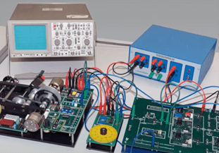
We’ve had similar types of projects done by existing Quanser users, such as in NYIT (see below). This can be integrated into the labs of an existing course, assigned as a final-year team project, used in a course “sprint”, and so on.
How do I get access?
This is a very flexible project-oriented design challenge that can be scaled to students with different experience levels and backgrounds. It can be integrated into the labs of an existing course, assigned as a final-year team project, used in a course “sprint”, and so on.
If you are an instructor interested in running this or learning about the project resources available, please contact us at info@quanser.com with the subject line “QUBE-Servo 2 Ball and Beam Design Project”. One of our Quanser engineers will contact with you and show you how to get started.
We also have a “Quick Start” version available that allows you to run the full controller and see if it would be right for your course. The hardware and software requirements are listed below.
Hardware/Software Requirements
- MATLAB/Simulink
- QUARC Essentials
- QUBE-Servo 2
- Webcam
- Ball and Beam (e.g. 3D printed beam with ping pong ball)
Final Remark: NYIT Capstone Ball and Beam Project
This project-based learning approach was first done with Ziqian (Cecilia) Dong, Associate Professor in the Department of Electrical and Computer Engineering at the New York Institute of Technology (NYIT) for the EENG 491 Senior Design Project in Spring 2011 and 2012.
The 4th year undergraduate students learned about control system design and implementation using the Rotary Servo Base Unit and Ball and Beam systems with the QUARC Real-Time Control software. Students had little experience with control systems or many had never used MATLAB/Simulink. After learning about control system design and implementation, they designed their own 2 DOF ball balancer systems using different ball position sensing techniques. For more information, refer to the paper that Prof. Dong and her colleagues presented at the 2012 ASEE annual conference, entitled AC 2012-2956: Infusing the Curriculum with Cutting Edge Technologies through Partnerships with Industry.