
Though we released the Autonomous Vehicles Research Studio last year, the development did not stop there. In this blog post, I will recap our work on the drone component of the research studio.
Some of you might have seen the video of our QDrone on a gimbal driving a virtual drone simulation:
We have been showing this demonstration at many events and conferences around the world. It is a perfect example of implementing the Quanser Method, a methodology we deploy when designing all our teaching and research systems. Following the Quanser Method, we distill any complex system into accessible isolated subsystems where we can interrogate the instrumented system and validate our models and assumptions iteratively.
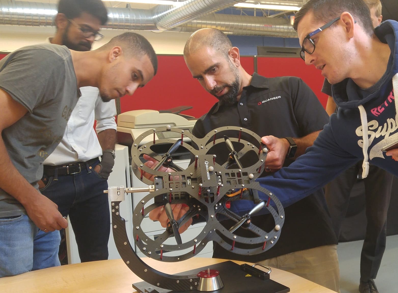
Testing the QDrone on a 2 DOF gimbal
In the case of the QDrone, we dealt with two main control systems governing all the 6 DOF states of a flying vehicle: its orientation (roll, pitch, yaw) and position (x,y,z). Although we had electro-mechanical properties of the drone (masses, inertias, thrust, etc.), we started with a single degree of freedom and validated our assumption and models first before expanding to multiple DOFs. The other benefits of isolating the problem into smaller states were the advantage of rapid control prototyping (RCP) and how we could iterate on our model-based controls approach to both predict and then optimally control the behavior in each axis.
Iterative Rapid Control Prototyping
To facilitate this RCP process, we designed a 2 DOF gimbal that would facilitate a roll (or pitch) and yaw of an attached drone. The gimbal was also instrumented with two high-resolution encoders to provide a true measurement of the drone’s orientation to validate the drone’s orientation estimation.
We started by focusing our efforts on a fast and reliable orientation estimation using a complementary filter that we developed. That is where having a transparent and fully instrumented system including the encoders on the gimbal came in handy. We iterated on the design of the estimation and introduced increasing noise (by turning on the drone motors) before settling on a fast and accurate yet robust orientation estimator.
Next, we used our dynamic model of the drone (roll axis) along with our previously characterized propulsion system (motors, propellers, drives) to validate our model and verify it on our experimental setup. With a validated and updated model, we then developed an optimal model-based controller and validated it on the single roll axis before reconfiguring the drone and verifying the same approach on the (almost) symmetric pitch axis. Although the yaw axis will exhibit different dynamics on the gimbal than in actual flight, we still deployed the same process on the yaw axis knowing there would be some changes to the controller values once the drone was in flight.
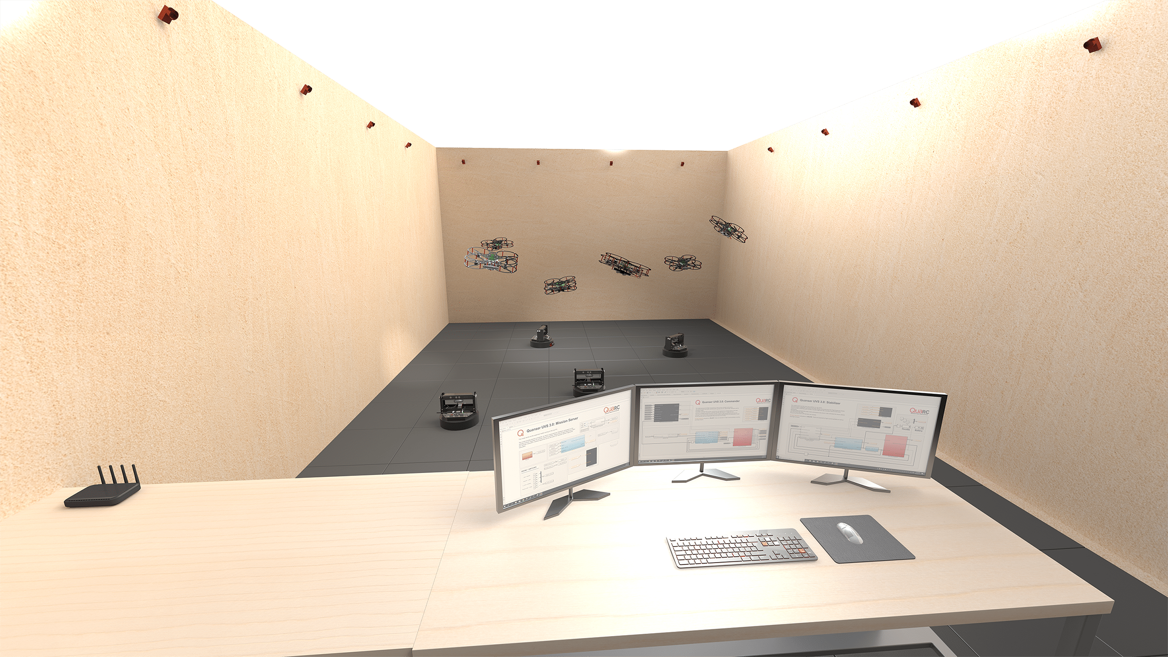
Virtual drone simulation and how we designed it
In parallel to the developments of the QDrone, we started experimenting with the UnReal Engine to allow rich 3D visualizations of our systems and applications (as well as fun videos like our Holiday video). We leveraged this integration and built a 3D model where we could visualize the QDrone’s orientation and position. But how can a drone fixed to a stationary gimbal fly? With the power of model and hardware in the loop simulations, we again leveraged the dynamic properties of the drone (masses, inertias, propulsion) to develop a dynamic model of its position in 3D space based solely on its orientation (estimate) and commanded thrust (force).
We now had a drone with a fast and robust stability loop (i.e., a loop that can be oriented in roll and yaw) along with a dynamic model that leveraged actual drone information and predicted its position in 3D space (pretending it was not fixed to a gimbal). The final step in this process was to develop the outer loop position controllers (taking xyz positions and commanding the drone’s roll, pitch, yaw and thrust to realize the desired position) and apply it to our working model with the drone stabilizer along with its dynamic position model.
But better than the description, check the end result in the video with two virtual drones below. The first virtual drone illustrates the desired position we would like the drone to travel to (along with the commanded orientation). The second drone illustrates the actual orientation of the real drone on the gimbal along with its model position. The commands cycle in a square motion and change once the drone reaches it’s desired position.
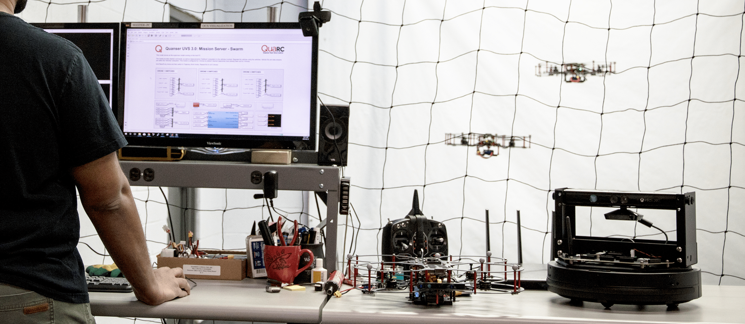
From simulation back to the real drone
The final step in this process was to transfer the model onto an actual flying drone. We can simply replace the estimated position with the actual position as measured by our localization cameras and replicate the virtual drone!
Final thoughts
The QDrone development took us on a journey from its initial validation on an instrumented gimbal through the virtual flight in a simulated space to finally taking off for real. In this world where reality and virtualization are blending and mixing, perhaps the question we posed initially isn’t as straight forward as it seems. Would a drone by any other name fly?
We truly benefited from having an instrumented gimbal as a part of our development process. By the way, we are considering adding it as part of our research studio offering. We see it as a great tool to facilitate a more accessible teaching platform and a safe starting point for more advanced flight control research applications. We would love to hear your thoughts on where you would benefit from such an addition!