Active Suspension

Advanced platform mass-spring-damper modelling and control
The Active Suspension experiment can be used for teaching and research based on the technology that has brought a new generation of vehicles to life. Active suspension technology is used in the automotive industry to continuously control the vertical movement of the vehicle wheel using an actively controlled actuator placed on the suspension axis. Similar technologies have also been used in train bogies to improve the curving behaviour of the train and the acceleration perceived by the passenger. The versatile platform can also be used to teach mass-spring-damper modelling and control at a fundamental level, as well as applications of IMU measurement and processing.
Gallery

Product Details
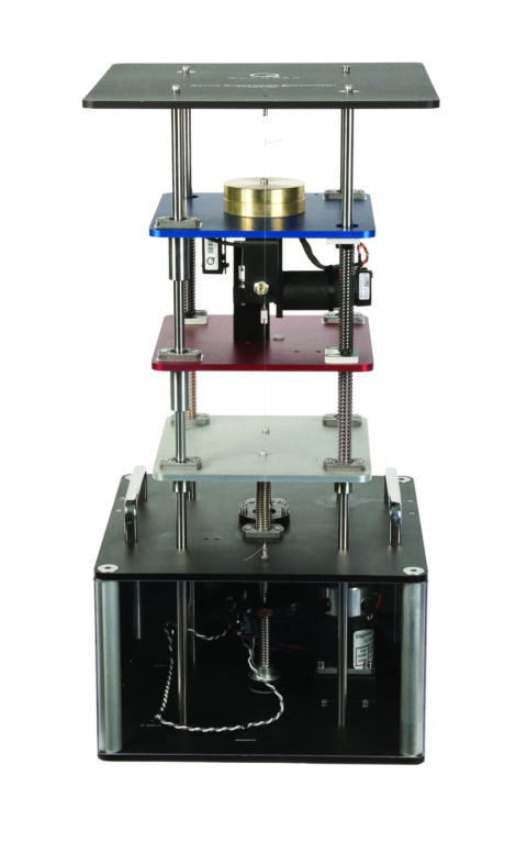
The Active Suspension consists of three masses that along stainless steel shafts using linear bearings and is supported by a set of springs. The upper mass (blue) represents the vehicle body supported above the suspension, the middle mass (red) corresponds to one of the vehicle’s tires, and the bottom (silver) mass simulates the road. The upper mass is connected to a high-quality DC motor through a capstan to emulate an active suspension system that can dynamically compensate for the motions introduced by the road. The lower plate is driven by a powerful DC motor connected to a lead screw and cable transmission system.
- Three high-resolution encoders used to measure positions of bottom and top masses as well as suspension deflection
- 226 W MICROMO brushless DC motor connected to capstan for active suspension control
- 70 W Magmotor brushed DC motor connected to belt-drive mechanism for road actuation
- Adjustable weight and spring stiffness
- Accelerometer measurements as sensory input
- Responsive belt-drive mechanism to simulate the road surface
- Accelerometer mounted on top plate to measure vehicle body acceleration
- Limit switch and protection circuit
| Dimensions (W x L x H) | 30.5 cm x 30.5 cm x 61 cm |
| Total Mass | 15 kg |
| Range of Motion | ± 22 mm (road), ±19 mm (tire), ± 25.4 mm (car) |
| Position Resolution | 0.002 mm/count (road), 0.005 mm/count (tire), 0.009 mm (car) |
| Stiffness | Adjustable from 0.4 to 2 N/mm |
| Excitation Frequency | Up to 15 Hz |
| Resonant Frequency | Configurable between 2 to 6 Hz |
| Accelerometer Sensitivity | 9.81 m/Vs² |
- Double mass, spring, damper system analysis
- Industry-relevant control requirements (ride comfort, suspension travel, road handling)
- Derivation of dynamic model
- Finding system state space representation
- Finding system transfer function model
- State-feedback control design using LQR
- Closed-loop state-feedback system simulation
- Implementation of the LQR-based state-feedback control on the Active Suspension system
- Open-loop system analysis of the system using sweep/chirp signal
The following additional components are required to complete your workstation, and are sold separately:
For Simulink
- QUARC® add-on for MATLAB®/Simulink®
- Quanser AMPAQ-L2 linear current amplifier
- One of the following DAQ devices:
- Quanser Q8-USB
- Quanser QPIDe
For LabVIEW
- Quanser Rapid Control Prototyping (Q-RCP) Toolkit® add-on for NI LabVIEW™
- Quanser AMPAQ-L2 linear current amplifier
- One of the following DAQ devices:
- NI CompactRIO with two Quanser Q1-cRIO modules
- Quanser Q8-USB
- Quanser QPIDe
Group Citation: Earthquake Engineering
Explore more: All Research Paper
Related Products
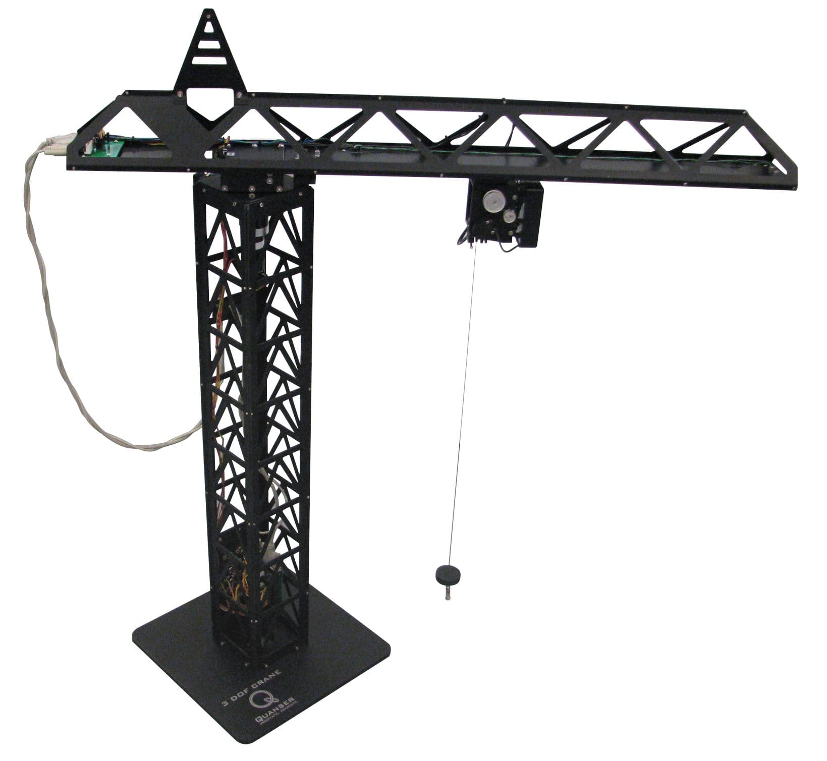
3 DOF Crane
THIS PRODUCT IS NO LONGER AVAILABLE.
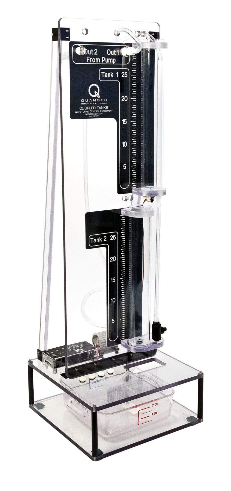
Coupled Tanks
Reconfigurable modeling and process control experiment
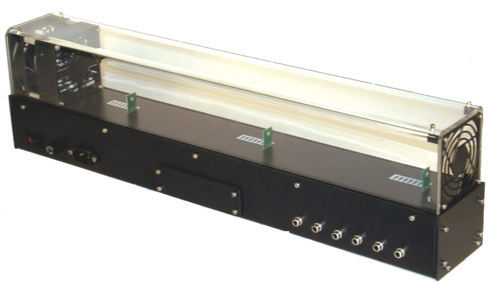
Heat Flow Experiment
THIS PRODUCT IS NO LONGER AVAILABLE.