Hello again! In the previous blog, I talked about the thought process that went behind developing Quanser’s serial manipulator platform – the QArm. Today, I want to show you how I was able to rapidly develop a pick and place application for the QArm serial manipulator by leveraging some toolboxes provided with MATLAB/Simulink. The application itself is rather simple, I wanted the QArm to move between three Cartesian positions – pick, place and home, while actuating the gripper to transfer an object between them.
Development using a Simulation
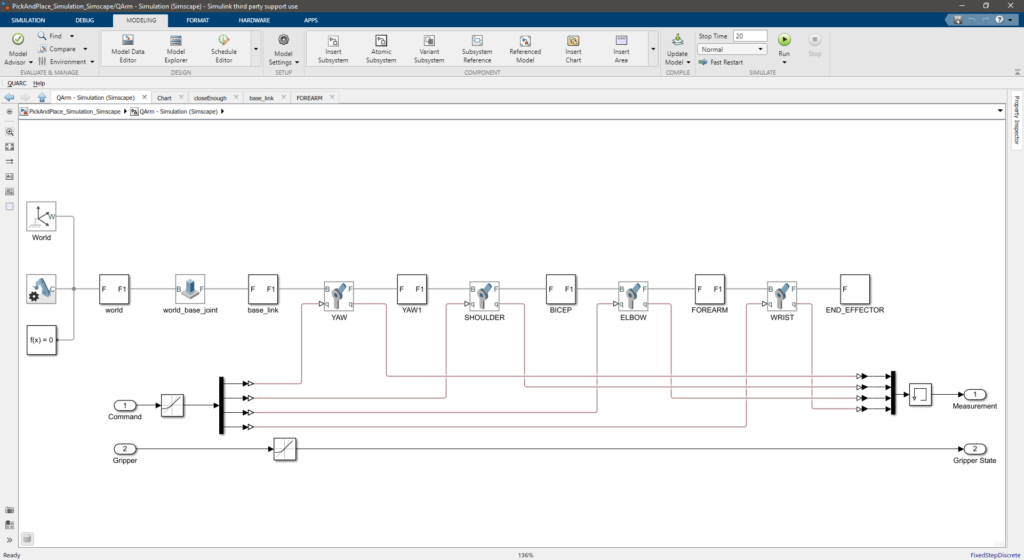
It all began with a Unified Robot Description Format (URDF) model. I pulled the URDF model into Simulink and created a Simscape Multibody model using the MATLAB command smimport (part of the Simscape™ Toolbox). Such a model includes the dynamic properties and kinematic configuration of your manipulator and allows you to simulate the motion of your object, complete with a visualization, all in a few steps . After the import, I modified the revolute joint blocks to select an actuation mode, but all the information regarding joint limits, link lengths, masses etc. were automatically imported, which is shown in Figure 1 below.
This model was placed in a subsystem labeled 1 in Figure 2. This gave me a mathematical model to test my code without risking failure on actual hardware. Although we prove analytical inverse kinematics solutions, I was interested in leveraging the URDF model further. The Robotics System Toolbox™ provides a variety of tools for robotic manipulators. I used the Inverse Kinematics block (labeled 2 in Figure 2) to convert the Cartesian task position commands for the end-effector (such as pick, place, home) into corresponding joint space configurations, which could then be sent to the Simscape Multibody model. This block uses an iterative solver to find the inverse kinematics solution, and aside from some tuning, needs nothing else but a Rigid Body Tree model. This is created once again from the URDF model by using the MATLAB command importrobot. To top it all off, the URDF representation of the QArm (available on Github right now) will also be seamlessly included with the Robotics Systems Toolbox in MATLAB 2021a. I also used the Get Transform block (labeled 3 in Figure 2) to complete the forward kinematics based on the same Rigid Body Tree, which allows me to convert the joint positions from the Simscape Multibody model back into task positions for control purposes.
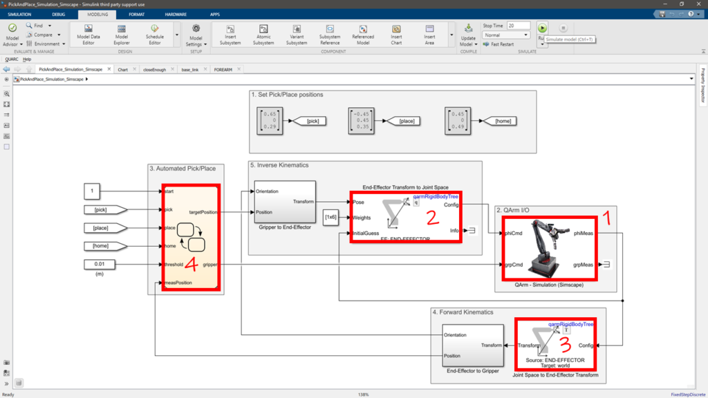
With the kinematics out of the way, the next step involved developing a logic routine to jump between these positions. I used Stateflow® to develop a straightforward state machine. The Chart block (labeled 4 in Figure 2) creates a new environment for you to analyze the state machine.
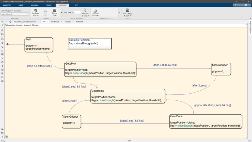
The graphical code you build is in itself the state flow diagram (shown in Figure 3), making the implementation elegant and easy to follow. Video 1 shows you what the robot motion looks like when I run the validation model.
Verification via a Digital Twin
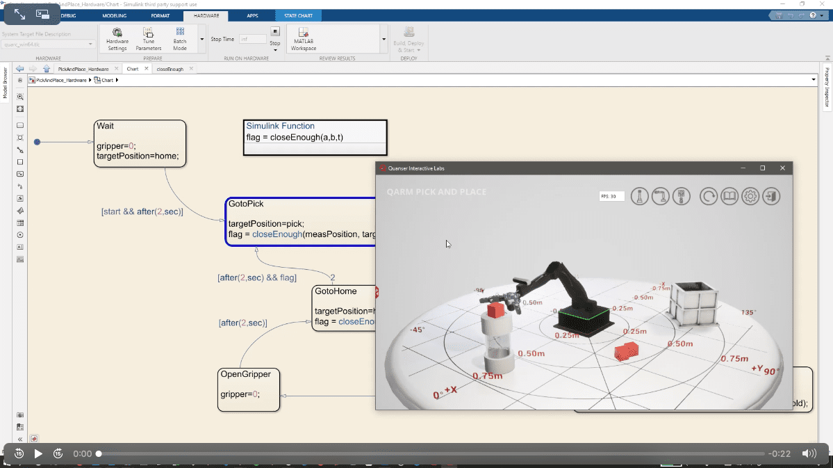
The URDF model does not have a gripper in it. So to ensure that the gripper was functioning before hardware deployment, I leveraged the Virtual QArm manipulator provided with Quanser Interactive Labs. Swapping out the Simscape Multibody model subsystem with another (labeled 5 in blue in Figure 4) allowed me to command the Virtual QArm.
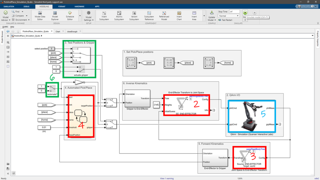
I also added some code (labeled 6 in green in Figure 4) that allowed me to pause the automatic operation, and manually move the arm to the pick, place and home positions (like task jogging in an industrial manipulator) to ensure that the positions were applicable to the Virtual QArm environment. The remaining code via the Robotic Systems Toolbox and Stateflow were left unaltered. Video 2 shows you the implementation on the Virtual QArm, along with how the Stateflow Chart block actually shows you the current state of the state-machine.
Validation and Deployment on Hardware
Now comes the fun part – watching it all work on the hardware. I replaced the Virtual QArm subsystem (shown in blue in Figure 4) with one for the physical QArm (labeled 7 in Figure 5).
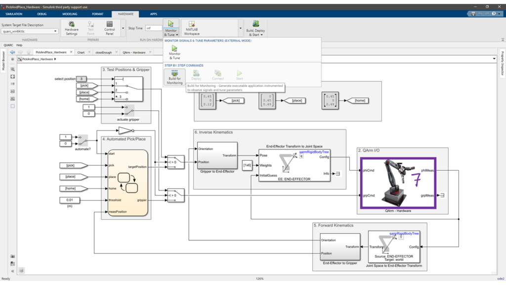
The remaining code was left unaltered. I used the manual code section to let my QArm know where the coffee was located, and where it can drop off the cup when done. Watch it go in Video 3. QArms have Monday mornings too you know!
These toolboxes allow you to safely test your logic on simulations, and then validate performance on real hardware. We also provide full robotics curriculum, numerous examples, completed documentation and analytical implementations for most robotic manipulator functions. If you want more information on that, or a run through on how this example was developed, don’t hesitate to reach out by leaving a message below. I am more than happy to get on a call with you. Until next time!