

Modelling a DC servomotor is one of the common examples used in control system textbooks and courses. Given that so many systems use DC motors, e.g. robot manipulator arms, it’s an important exercise to go through as well.
If you ever compared your DC motor model with the actual hardware, you probably found that it did not quite match. That is very common and, frankly, is usually fine as many applications do not need an extremely accurate model. In addition, if the model is too complicated then it makes it more difficult to conduct your control design. However, it can be valuable to investigate the sources that cause this mismatch and to use more advanced software methods to get a more representative model without having to spend a lot of time doing it.
In this blog, I will introduce how to use the Simulink® Simscape™ environment to model the Quanser QUBE-Servo 2 and show one method to identify the Stribeck and Coulomb friction.
Why doesn’t my DC Motor Model Match the Hardware?
After modelling the DC motor using the familiar equations, you may notice that its response does not quite match the hardware. Sound familiar? You double check the motor parameter values, but there is still a discrepancy between the speed measured on the hardware and the simulated speed from the model. Most engineers dealing with servomotors will face this situation in their academic or industrial career.
What is the most likely cause of the model not matching the actual system? There are two main reasons:
- Parameter uncertainty
- Unmodelled dynamics
The model developed may be based on the nominal parameters. If the model is based on the motor parameters from the specification sheet (e.g. motor resistance, back-emf constant) then those parameters may not be 100% accurate. There is often a slight tolerance. That is one common source that causes model discrepancy.
Unmodelled dynamics includes elements that have been neglected in the model. Here are a few commonly ignored or deemed as being “negligible”:
- Motor inductance
- Data-acquisition device quantization on the D/A and A/D channels
- Sampling effects of microprocessor or PC/laptop
- Quantization of the encoder
- Saturation of the motor amplifier/motor limits
- Friction
If the motor inductance is small, then it does not have a large effect on the response. The effects of the D/A and A/D conversion is quite minimal when using a DAQ device that has at least 12-bit resolution. Sampling effects also do not have a huge effect when running at a fast and deterministic rate, i.e., 500 Hz or more. Encoder quantization causes issues when taking the derivative of the measured signal to find the angular rate (due to the small discrete steps). However, in this case, we are using the digital tachometer that computes the velocity directly from the encoder counts to obtain a smooth rate measurement, so encoder quantization is not going to be issue.
Friction, on the other hand, is the most likely culprit. While the friction in the QUBE-Servo is quite low, it is inherent in any rotary DC motor system.
Modelling the QUBE-Servo 2 in Simulink and Simscape
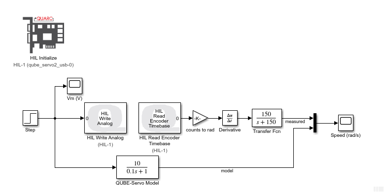
As discussed in one of my previous blogs, you can use the standard Simulink library blocks to build the block diagram representation of the DC motor, i.e. based on its equations of motion and known motor parameters. Another way is to model the motor as a first-order transfer function, as shown below. The DC gain and time constant parameters of the servomotor are measured from the step response and the model is defined using the Transfer Fcn block in Simulink.
Another method is using the Simulink® Simscape™ toolbox. This powerful toolbox offers numerous advantages. Leveraging its wide collection of blocks enables you to obtain a more accurate model without putting much more effort. It’s also great for users that are more comfortable modeling a system from a component-based framework rather than using transfer functions or state-space equations.
DC Motor Model in Simscape
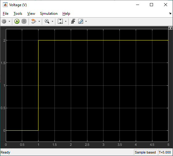
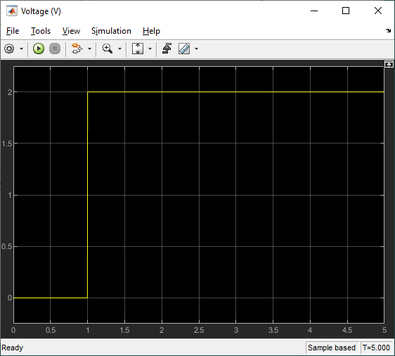
The QUBE-Servo 2 is modeled using the DC Motor and Inertia blocks from the Simscape Foundation Library. A 2V step voltage is applied using the Controlled Voltage Source block and the corresponding motor current, angular position, and angular velocity are displayed on scopes.
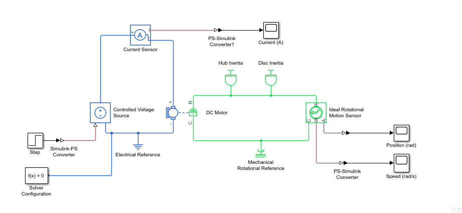
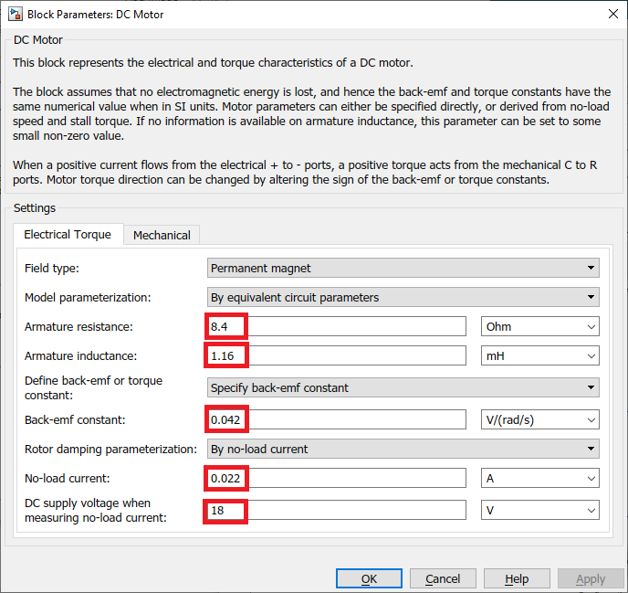
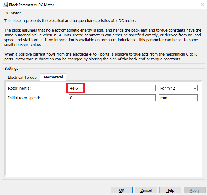
The DC Motor Simscape block makes it easy to model a DC motor. Based on the DC motor specification sheet; we enter the various parameters: motor resistance, inductance, back-emf constant, rotor damping and rotor inertia. Note that the rotor damping here is specified using the no-load current and DC supply voltage (since this was not supplied on the specification sheet).
Model Validation
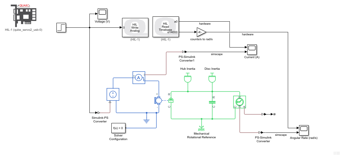
We can run the Simscape model in parallel with the actual QUBE-Servo 2 hardware using the QUARC Real-Time Control software, as shown in the Simulink model below. The QUBE-Servo 2 is interfaced using the QUARC HIL Initialize, HIL Read Timebase, and HIL Write Analog blocks. The HIL Read Timebase block is configured to read the on-board tachometer and current sensor. The HIL Write Analog block applies a voltage to the motor through the amplifier.

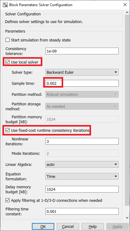
QUARC uses the MATLAB and Simulink Coder to generate external code and runs that in real-time. Since we are running the code on an external target (i.e. the PC/laptop CPU), the Simulink model must be setup to use a fixed-step solver. In this case we are using ode4 solver method. The Solver Configuration block can be configured to simulate a Simscape model with a fixed-step solver as follows:
- Select the Use local solver option and set the Sample time to match the rate of the Simulink model (i.e., the control loop period of the QUARC controller).
- Select the Use fixed-cost runtime consistency iterations option. Here we kept the default settings.
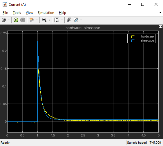
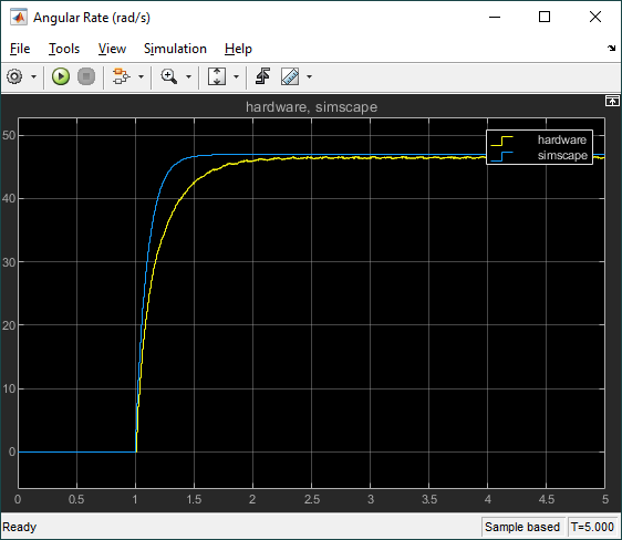
We can now run this model in QUARC to compare the response between the Simscape model and the QUBE-Servo 2 system.
This model response matches the hardware response fairly well and, for most control design, this would be fine. However, we notice that the model has a faster response than the actual hardware and the steady-state value is slightly different. As discussed earlier, the most likely reasons for this discrepancy are friction and inaccurate motor parameters.
Modelling Friction
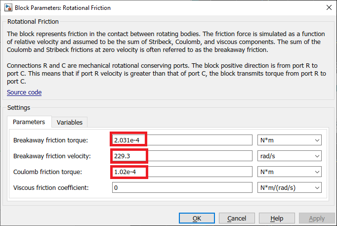
There are different models of friction. The most common one being Viscous friction and Coulomb friction. Here we will use the Simscape Rotational Friction block (shown below) to model the friction in the DC motor.

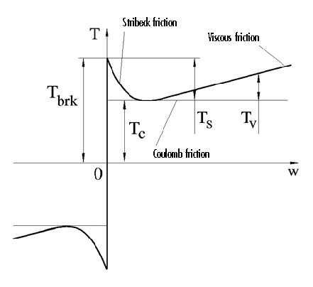
The Rotational Friction block represents friction torque as the sum of the Stribeck, Coulomb, and viscous friction, as shown below.
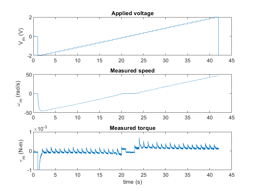
The Simulink model below is used to find the Stribeck and Coulomb friction. The Simulink Repeating Sequence Stair block applies small step inputs starting at -2V up to 2V at 0.1V increments.
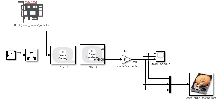
The voltage is applied using the QUARC HIL Write Analog block and the HIL Read Timebase block is used to measure the current and speed of the QUBE-Servo 2. The measured results are saved in a MAT file using the QUARC To Host File block. The measured results are shown in the figure below.
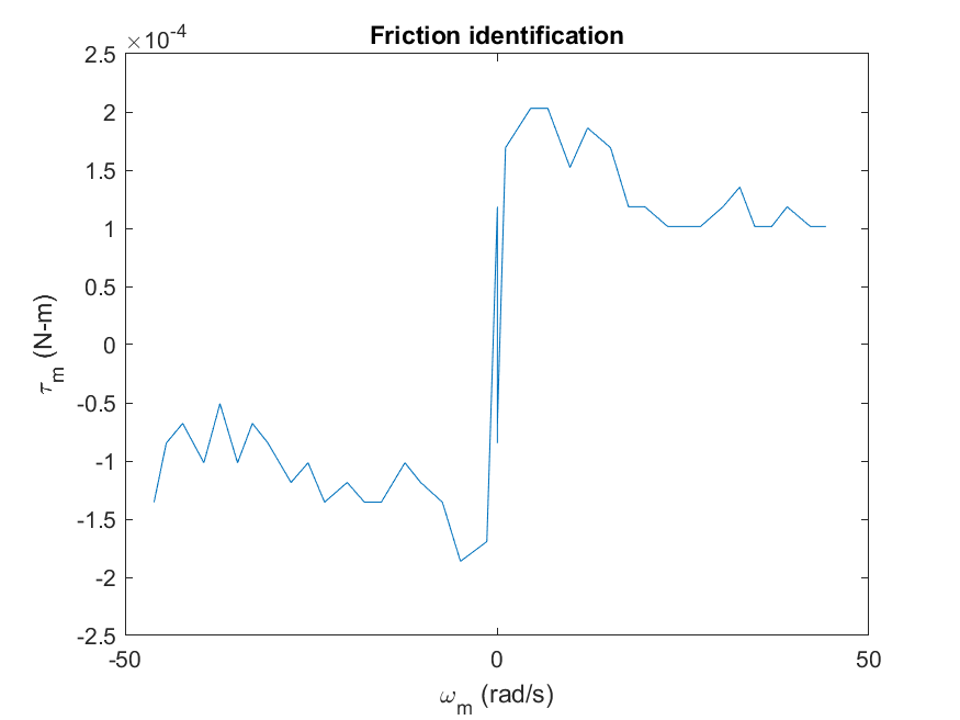
The torque applied is based on the measured current, I_m, using the formula tau_m = k_t x I_m, where k_t is the motor current-torque constant. The measured torque and speed are then plotted in order to identify the Stribeck and Coulomb friction, as shown in the figure below. Here we find that the breakaway friction torque is approximate T_brk = 0.000203 N-m and the Coulomb friction about T_c = 0.000102 N-m.
These parameters can now be entered in the Rotational Friction block. Note that the Viscous friction was defined earlier with the rotor damping in the DC Motor block, so it does not need to be specified here.
Model Validation with Friction
The Rotational Friction block is added to the DC motor model in the Simulink model developed earlier. We can now assess if modelling the friction improves the accuracy of the model by running it in parallel with the hardware.
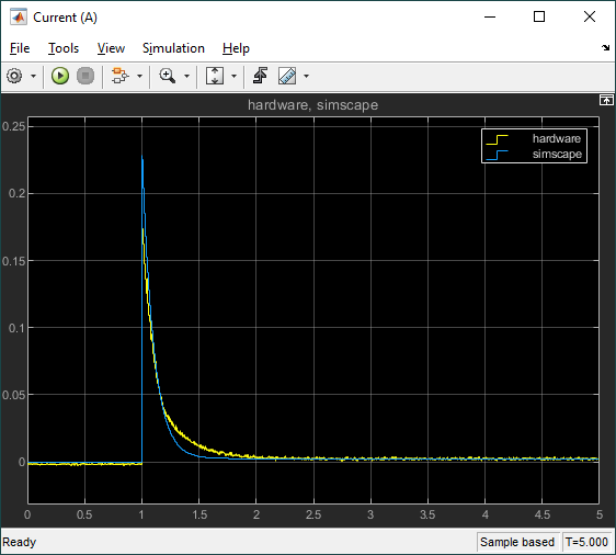
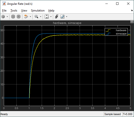
The response when running the Simulink model in QUARC is shown below.
Comparing the speed between the simplified model and this second model that incorporates Stribeck and Coulomb friction, we see the final steady-state value speed in the second model is more accurate (i.e. matches the hardware response more). The response time did not change significantly, therefore this discrepancy is most likely due to inaccurate parameters (e.g., the motor resistance, motor torque constant).
Takeaways
In closing, here is a summary of what was illustrated:
- Modeling a DC motor: overviewed different ways to model a DC motor system in Simulink and Simscape
- Model inaccuracy: discussed the different sources that can cause a discrepancy and focused on the two most likely culprits when modeling a DC motor – inaccurate motor parameter and friction.
- Introduction to Simscape: Showed how to use Simscape blocks to easily model a DC motor system – with or without friction.
- Friction identification: Summarized one way to identify the Stribeck and Coulomb friction.
- Running Simscape in real-time with QUARC: Highlighted a few key steps that are needed to configure a Simscape-based Simulink model for fixed-step to run with QUARC. This way, both the model and hardware can be run in parallel to perform model validation.
Hope some of this material is beneficial to you. Please send us your questions and comments.
Resources
For more information, please see the following:
- See the Quanser Friction Identification lab supplied with the QUBE-Servo 2 courseware to find the Coulomb and Viscous friction.
- See the Quanser System Identification lab to measure the motor resistance and back-emf constant experimentally.
- Simscape product page: https://www.mathworks.com/products/simscape.html