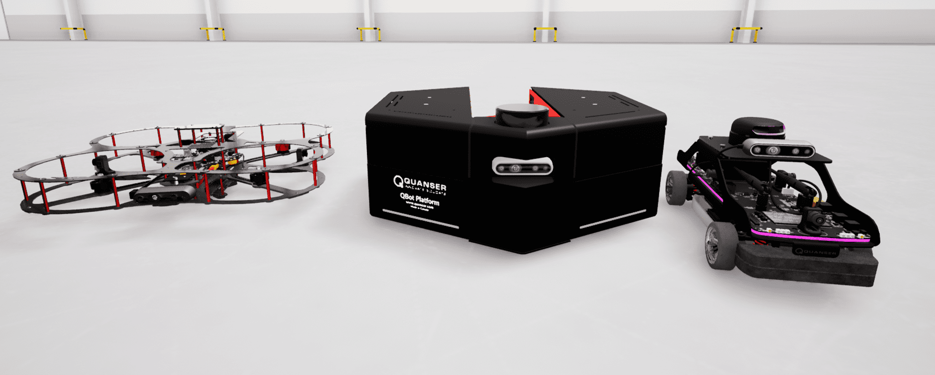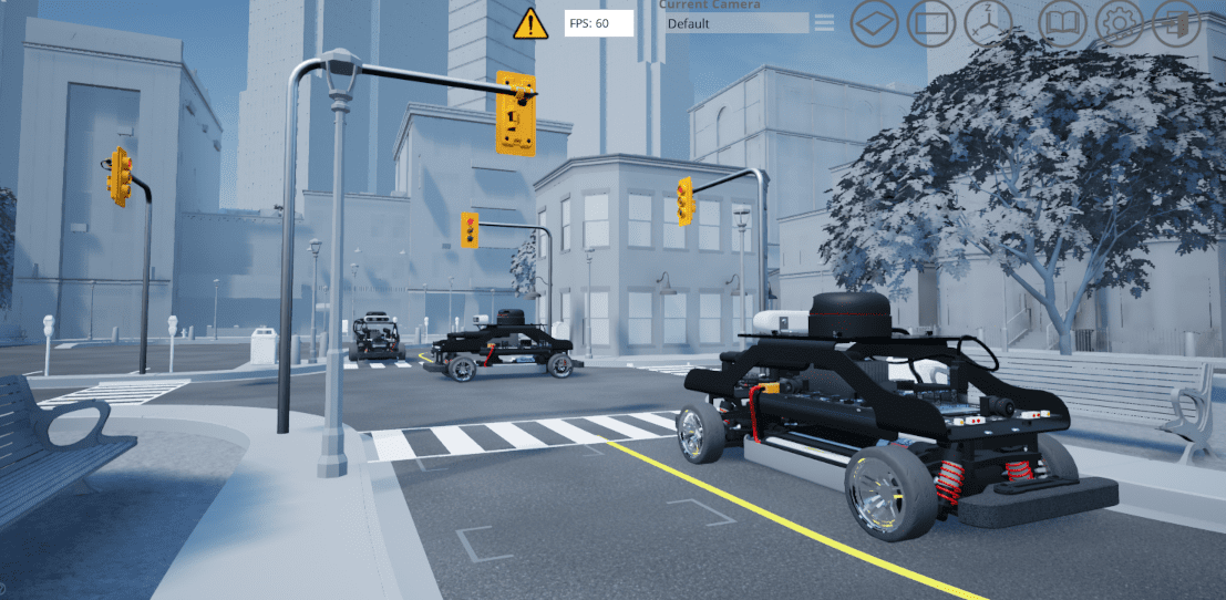

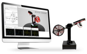
 We have recently launched our new Quanser Interactive Labs (QLabs) platform. As a member of the Academic Applications team that designed the virtual experiments, I would like to share some insights into the design process of the motor model for one of the virtual systems, the QLabs Virtual Quanser AERO.
From the Physical System to a Virtual Twin
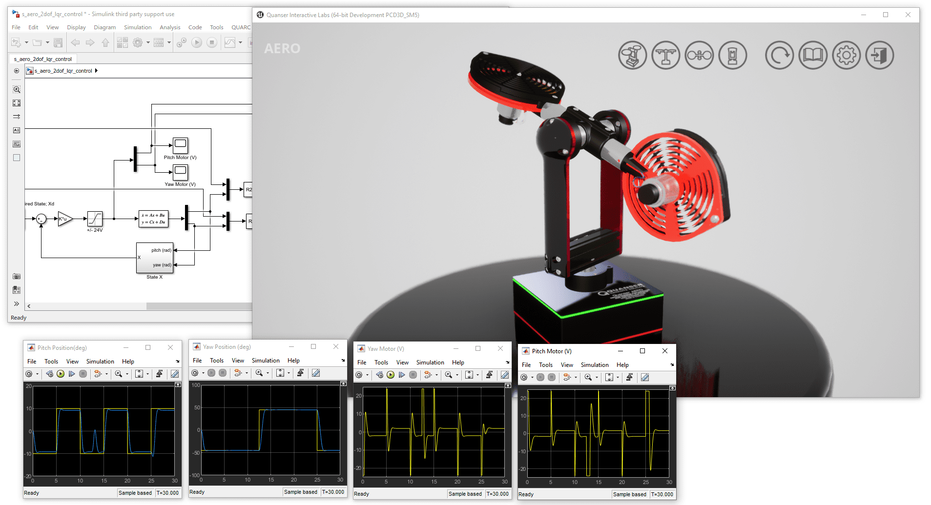
Given that we are talking about a virtual Quanser AERO, the behavior of the motor in the virtual environment will be slightly different than in the real world. Since our goal is to provide users with real-world experience when working with our virtual experiments, we wanted to model the motor as accurately as possible. So how did we do that? Without further ado, let’s look at the motor model in Simulink:
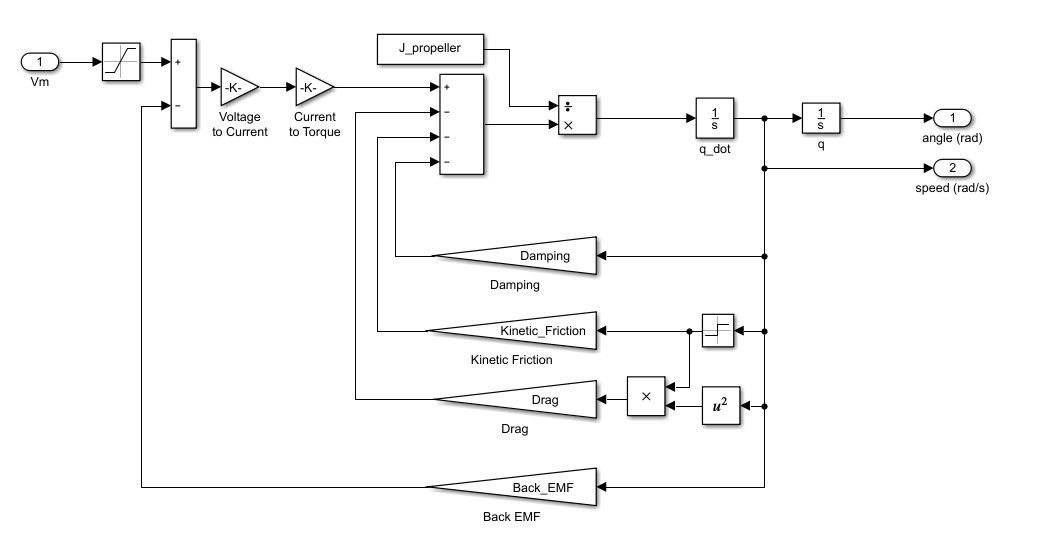
In the model, we took the voltage as an input and the motor speed and its position as an output. All the feedback loops that you see are the terms that helped us make the simulation similar to the real-world.
Given that the parameters such as the moment of inertia, terminal resistance, back EMF, and torque constant are provided, we started with structuring the general motor model that would be theoretically functional in a perfect environment. Then we looked at the internal losses that are created when the motor is moving.
Dealing with Damping and Non-linear Behavior
The first term we looked at was the damping. The damping is created when the motor is shorted. The higher the speed, the larger resistance the damping will generate. Therefore, the damping ratio is multiplied by the speed of the motor and subtracted from the total torque generated by the motor. According to the definition of the kinetic friction, we can treat it as a constant so it is subtracted from the total torque. Note that since the motor can spin in both directions, we added a sign block. That ensured the friction is always against the motion of the motor.
During the testing of the motor, we also observe a non-linear behavior. It is created by the drag that is generated by the AERO’s propellers. The higher the speed of the motor, the larger the drag it will generate. Hence the square block to reflect that non-linear effect.
Why Does it Matter?
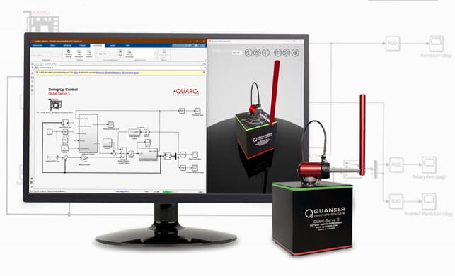
After you finished reading about our design process, you may ask “OK, what do we do with this model?” Well, if we look closer at it, this model can actually generate more outputs than just the position and the speed of the motor. The motor current and torque are calculated in this model as well. Torque is really important since the whole Quanser AERO movement is generated by the thrust and torque. Now that we got the torque, we can use it to calculate the thrust. The model can also be applied as a general motor structure for many other systems using a DC motor, such as QUBE-Servo 2. The design of this plant won’t be perfect so the tuning process is equally important which usually will take a significant amount of time.
Hopefully, this blog post illustrated the amount of effort we put into modeling the virtual experiments and validating them on real hardware. Our goal was to give you the same experience as when working with physical systems in a lab. This video shows you how the QLabs Virtual Quanser AERO works – including the motor model I introduced above:
Want to try the QLabs Virtual Aero yourself? We offer instructors a free trial – just fill out the form!