
Reinforcement learning (RL) is a subset of Machine Learning that uses dynamic data, not static data like unsupervised learning or supervised learning. Reinforcement learning is used in many different applications, such as training computer programs to perform certain tasks to autonomous vehicles. It is also used in control systems. Given its popularity, I thought I use the Reinforcement Learning Toolbox™ by MathWorks to balance the pendulum of a Quanser QUBE-Servo 2.
The main components in reinforcement learning to control a dynamic system like a water tank, DC motor, or active suspension system is illustrated in Figure 1.
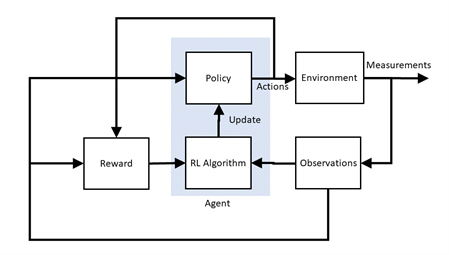
Here is a brief description of the components involved:
- Environment is everything that exists outside the agent. This includes the plant but also any other effects such as measurement noise, disturbances, filtering, and so on.
- Policy uses observations and reward signal from the environment and based on these, applies action to the environment. Different policies are akin to different types of control methods, e.g., PI, PD, PID.
- Reinforcement Learning Algorithm: Updates the policy based on the observations and reward signals, e.g., as the environment changes.
- Reward is a function used by RL to know when the system is approaching its objective or task, e.g., balancing the pendulum. It is similar to a cost function used in Linear Quadratic Regulator (LQR) based control except a reward function tries to maximize the value (i.e., not minimize it).
- Observations are the set of measured signals (e.g., position and velocity of a DC motor) that are used by the RL algorithm, reward function, and policy.
- Actions are the set of the control signals (e.g., motor voltage), as determined by the policy, going to the plant.
Reinforcement Learning Workflow
The steps to design a reinforcement learning agent can be summarized as follows:
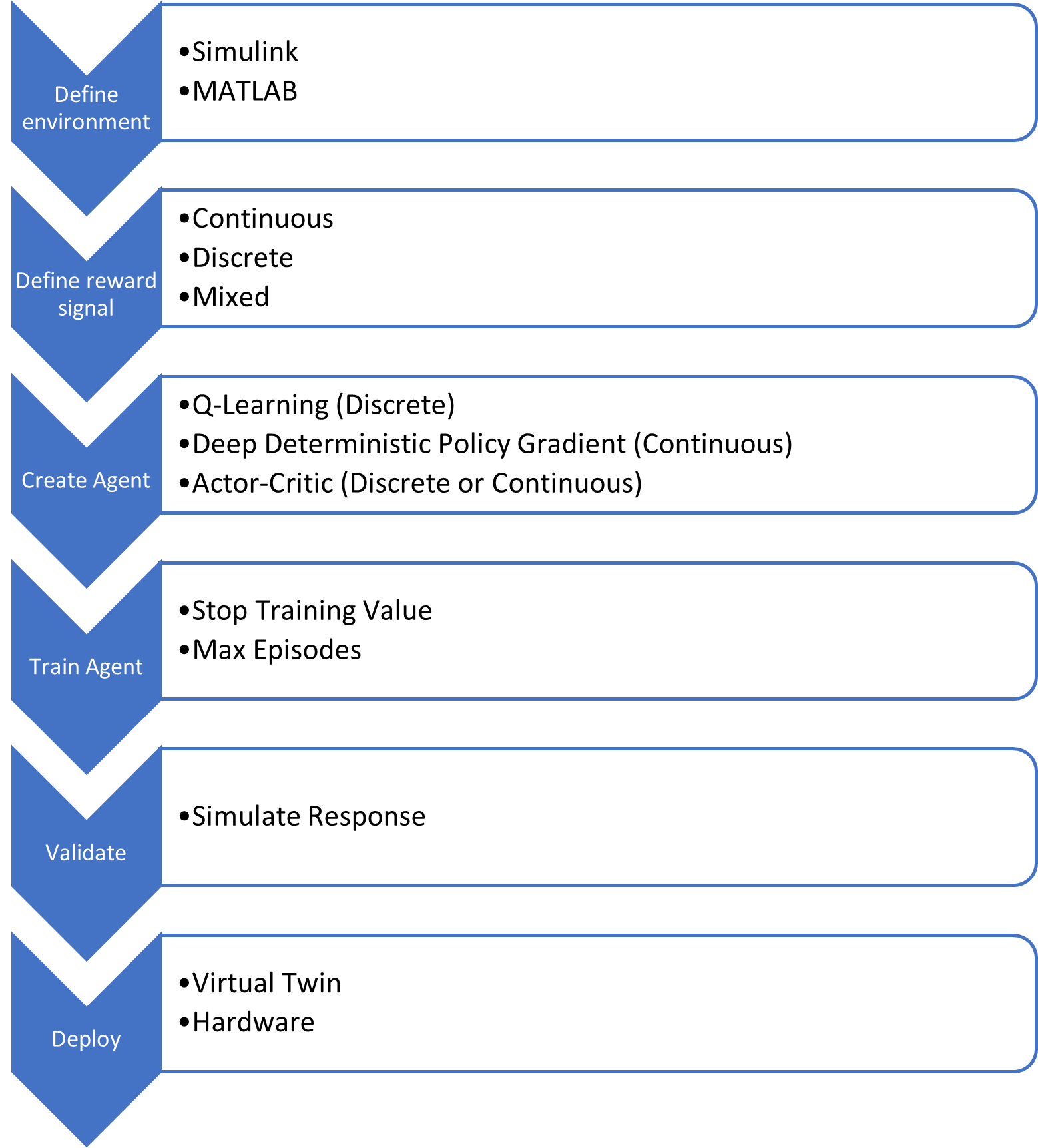
The workflow will be applied to the QUBE-Servo 2 Inverted Pendulum application in the next section.
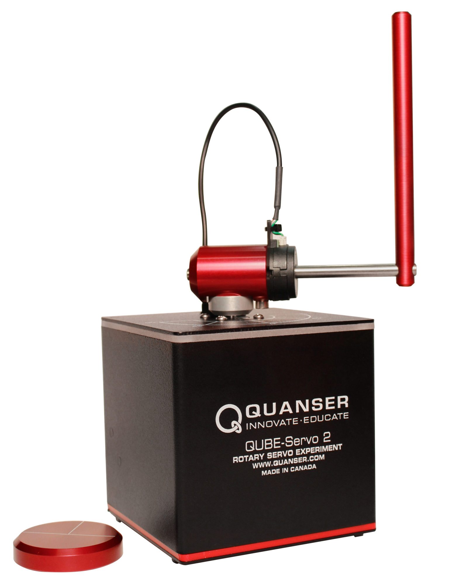
QUBE-Servo 2 Inverted Pendulum Reinforcement Learning Design
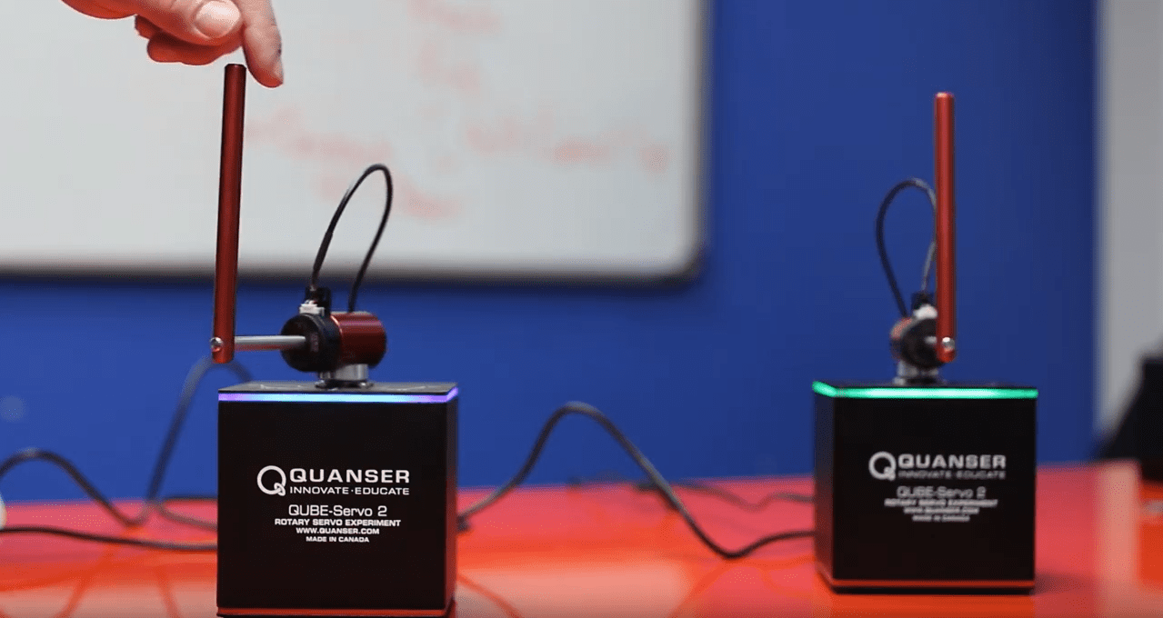
The QUBE-Servo 2 Inverted Pendulum system, shown below, has two encoders to measure the position of the rotary arm (i.e., the DC motor angle) and the pendulum link and a DC motor at the base of the rotary arm.
The Simulink® model used to train the RL agent for this system is shown below.
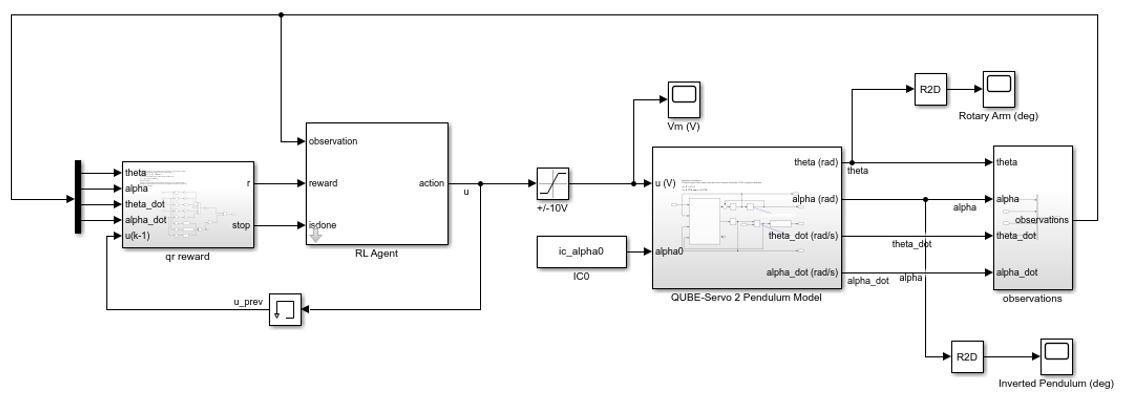
The main RL components such as the reward, observations, and environment shown in Figure 1 are defined in the Simulink model above.
Environment
The environment used to train the agent is a nonlinear dynamic model of the QUBE-Servo 2 system and is defined in the Simulink QUBE-Servo 2 Pendulum Model block. Nonlinear models represent the hardware dynamics more accurately and over a larger range. A model-based RL training method is being used for this application but there are model-free methods that use the actual hardware in the training process.
Reward and Stop Signals
The qr reward subsystem contains the reward and stop signals. The stop signals are used to stop the training session if the system does not satisfy certain conditions. The training episode is stopped when any of these conditions holds:
- Rotary arm exceeds +/- 60 deg, |Θ| > π/3
- Inverted pendulum angle goes beyond +/- 10 deg, |α| > π/18
- Motor voltage exceeds +/-5 V, |u| > 5
The stop signals are also incorporated into the rewards signal to penalize the agent, i.e., lower the score, when any of those conditions occur. Adding this penalization improves the chances of training a successful policy.
The reward function used for the QUBE-Servo 2 rotary inverted pendulum is:
![]()
The quadratic function rewards the agent when the rotary arm stays within the 0 deg position, the pendulum is balanced, and the control effort/motor voltage does not go too high. It was found that quadratic-based reward signals are easier to tune and increase the likelihood of training a successful policy.
Observation and Action Signals
For the rotary inverted pendulum there are four observation signals – the angular position and velocity of the rotary arm and the pendulum link, i.e., [Θ, α, Θ_dot, α_dot], and one action signal – the motor voltage, Vm.
Creating and Training the Reinforcement Learning Agent
The MathWorks Reinforcement Learning Toolbox™ includes several different types of agents that can be used to generate a policy. The Deep Deterministic Policy Gradient (DDPG) agent is chosen for this application because:
- It can output a continuous action space
- Already used in existing pendulum applications
The agent is created in MATLAB and uses the environment, reward, observations, and action signals that are defined in the Simulink model. The training is performed in MATLAB using the train command. The RL Agent block contains the policy that is trained by the RL algorithm to control the system.
Key Factors for Training a Successful Agent
Reinforcement Learning has a lot of different parameters. Here are some of the most important aspects in training an agent that will successfully balance the inverted pendulum:
- Reset function that randomizes the initial position of inverted pendulum. This is needed for the RL agent to be able to balance the pendulum within a large enough range, i.e., when the inverted angle starts between +/-10 deg from the inverted balanced position.
- Stop signals are used to stop a training episode when a system, for instance, exceeds certain limitations of the physical hardware. The stop signals shorten the total training time of the agent.
- Quadratic-based reward signal that includes penalties on the stop signals. Quadratic-based functions can make it easier to find a good candidate to train the RL agent.
RL Design Process
The design goals are the following:
- Pendulum can be stabilized in the nonlinear model-based simulation when the pendulum is initialized between +/- 10 deg.
- Pendulum can be stabilized in the QLabs Virtual QUBE-Servo 2 digital twin when the pendulum is brought up “manually”, using the “Lift pendulum” button.
Training an RL agent presents a different set of challenges than model-based design. The main challenges with RL are:
- Selecting the reward signal.
- Many design variables.
- Long training times.
These are the main design parameters that were changed in the training sessions:
- Reward Signal: Quadratic weights used in the reward function.
- Initial Pendulum Angle Range: Determines the range used by the reset function to randomize the initial position of the inverted pendulum.
- Final Time: Duration of simulation. Making the simulation time as small as possible while allowing enough time for the system to be balanced leads to shorter overall training times.
- Sample time: Sample time of the Simulink model – for both the environment and the agent. Selecting the lowest sampling rate needed to perform the task will keep the training times reasonable.
Results
Once a successful agent is trained, how well the policy balances the pendulum is tested in simulation, on the virtual twin of the QUBE-Servo 2, and on the actual QUBE-Servo 2 hardware.
Simulation
The agent is first tested in the same Simulink model that was used to train the agent, shown in Figure 3. As discussed previously, this Simulink model uses a nonlinear model of the rotary pendulum system.
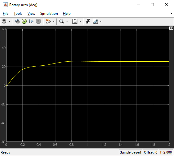
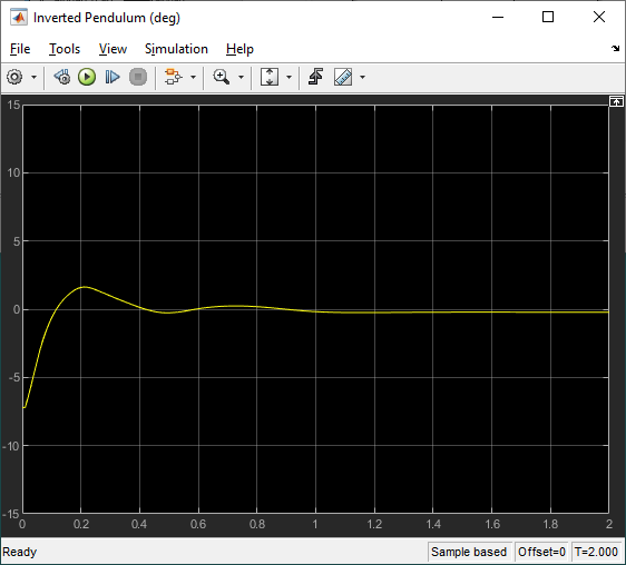
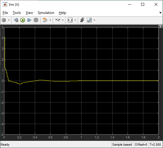
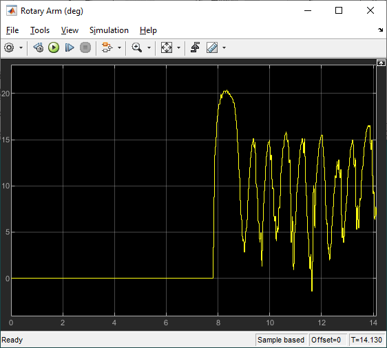
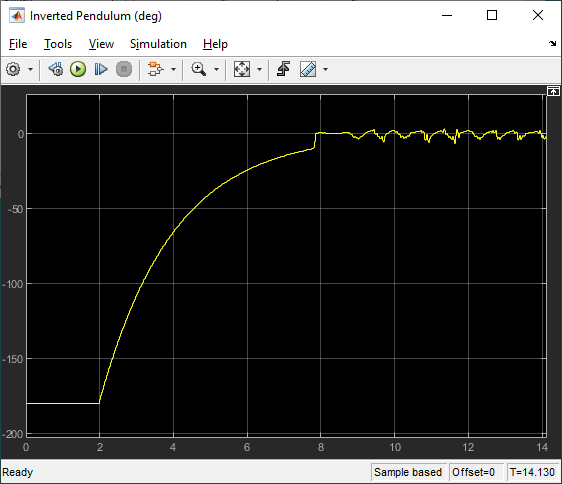
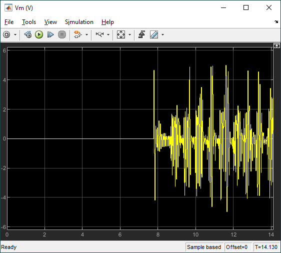
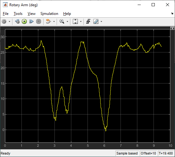
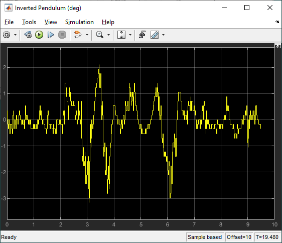
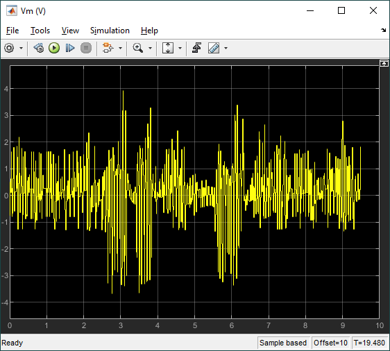
The response of the rotary arm and pendulum when it starts at approximately -7.5 deg from the upright balance position is shown in the Rotary Arm (deg) and Inverted Pendulum (deg) scopes and the corresponding voltage applied to the motor is shown in the Vm (V) scope. As shown in the responses below, the pendulum is balanced quickly (in less than 0.4 sec), similarly as with the LQR-based control, and the control signal is smooth – making it realizable on the virtual twin and hardware.
Virtual Twin
The Simulink model shown below interacts with the QLabs QUBE-Servo 2 Virtual Experiment. Like the Simulink model used to train the agent shown in Figure 3, this model includes the reinforcement learning RL Agent block. Since the pendulum in the virtual system starts in the hanging down position, as in the hardware, an enable balance control switching mechanism is also incorporated so that the control signal is only applied when the pendulum is brought up within +/- 10 degrees of the upright vertical position.
The scopes below show the response when the pendulum is rotated from the bottom downward position to the upward position. The agent engages when the pendulum is within +/- 10 deg from the vertical upright position.
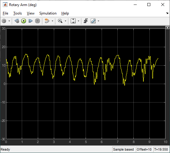
The scopes below show the response when the system is in steady-state balance mode.
Below is a video showing the QLabs QUBE-Servo 2 Virtual Experiment in action with RL.
The virtual twin uses a more representative model of the system than the nonlinear model that was used for the training. It incorporates DC motor friction and signal conditioning effects. As a result, the rotary arm tends to oscillate more about balance position which is more in-line with how the hardware behaves when running the balance control. This test provides some validation that the reinforcement learning agent can be realized on the actual hardware.
Hardware
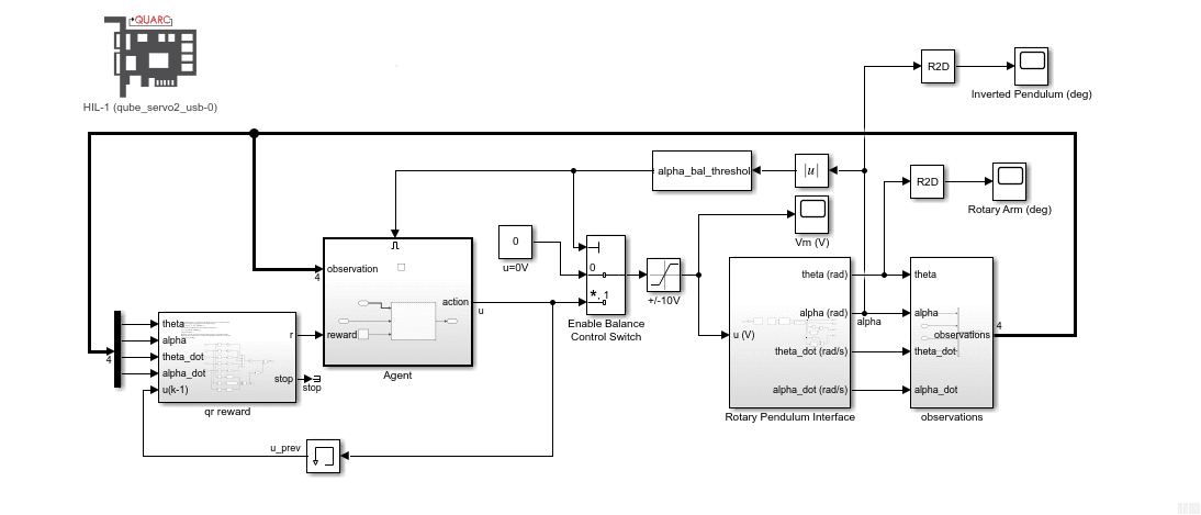
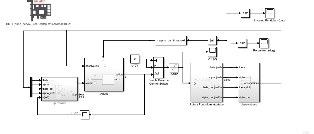
The agent was then implemented on the hardware using the following Simulink model with the Quanser QUARC real-time control software.
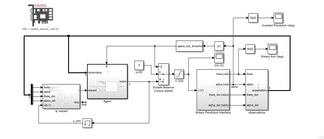
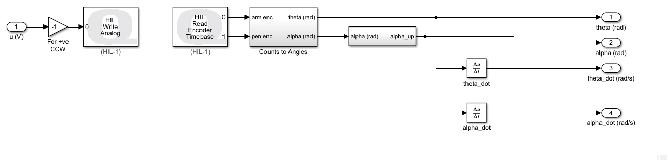
The RL Agent block runs the policy, and the hardware is interfaced using the blocks from the QUARC Targets library. As shown below, the QUARC HIL Write Analog applies a volage to the DC motor and the HIL Read Encoder Timebase measures the angles of rotary arm and pendulum through the encoders.
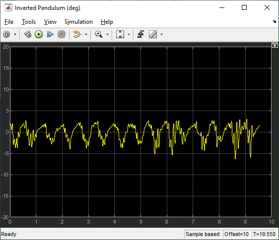
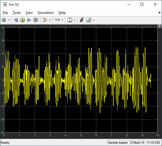
The response is like the virtual twin with the rotary arm oscillating back-and-forth to balance the pendulum. In this case, the rotary arm oscillates about a non-zero point of about 15 deg. The motor command signal is a bit noisy, as in the virtual twin, as well.
Below is a video showing the RL balance control in action on the QUBE-Servo 2 system.
Final Remarks
While some improvements can be made, this approach demonstrates that reinforcement learning can successfully be used for advanced control tasks in electromechanical systems and is realizable on actual hardware. There have already been a host of examples showing how RL can be used to balance and swing-up pendulum systems. While using RL for control system applications has already shown some benefit, it is still in its infancy and will become a more powerful and easy-to-use technique in the next few years.
Next Steps
- Simplify and have a more systematic design process to create a realizable RL policy. Find what factors influence the response the most, e.g., faster response, minimizing control signal noise.
- Design a RL controller to swing-up and balance the QUBE-Servo 2 rotary pendulum system.
Resources
- MathWorks® Reinforcement Learning eBook:
https://www.mathworks.com/campaigns/offers/reinforcement-learning-with-matlab-ebook.html - Reinforcement Learning Tech Talks videos by Brian Douglas:
https://www.mathworks.com/videos/series/reinforcement-learning.html - MathWorks® Reinforcement Learning Toolbox™ product page:
https://www.mathworks.com/products/reinforcement-learning.html - MathWorks® Reinforcement Learning for Control System Applications page:
https://www.mathworks.com/help/reinforcement-learning/ug/reinforcement-learning-for-control-systems-applications.html - Quanser Interactive Labs:
https://www.quanser.com/digital/quanser-interactive-labs/