
In the previous “intermediate control” blog post series, we highlighted the Ball and Beam and Magnetic Levitation systems as a great way to introduce the advanced control concepts without requiring students to use state-space techniques. Another great plant to use in such mid-range situations, when your course is not really the “introduction to controls,” but not quite at the “modern/advanced control” level either, is the Coupled Tanks system. Let’s have a look at what you can do with this process control experiment – and thanks to its flexibility, there’s a lot!
A highly reconfigurable hands-on process control experiment
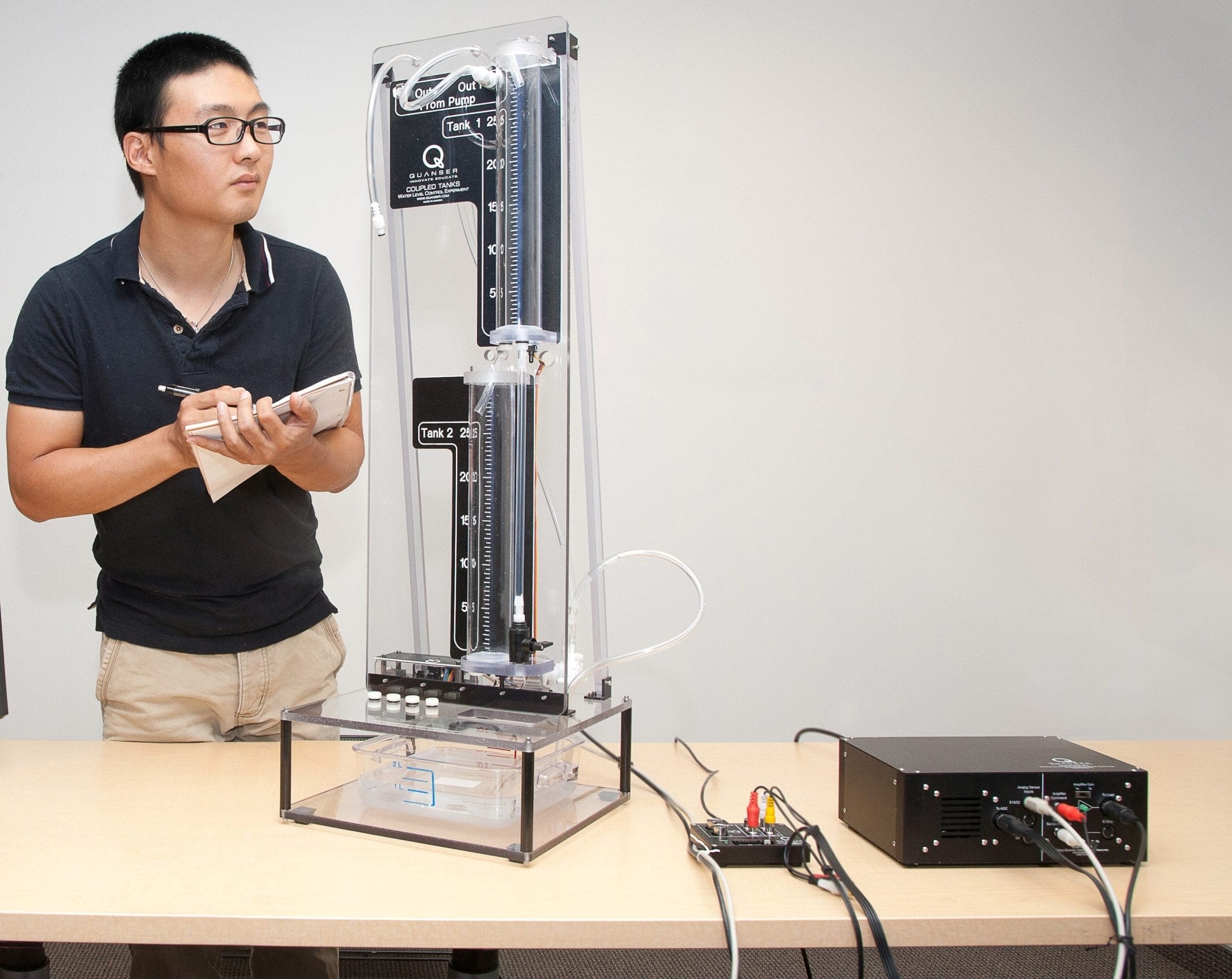
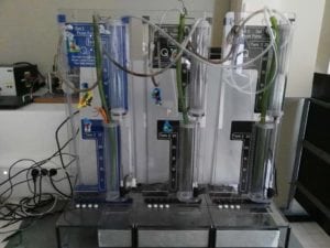
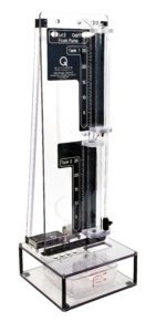 The Quanser Coupled Tanks is a nonlinear, reconfigurable system for liquid level/process control experiments. Quanser designed it in collaboration with Professors Karl Åström and Karl Henrik Johansson. The system consists of two tanks and a pump. Each tank is instrumented with a pressure sensor to measure the liquid level.
One of the great features of the Coupled Tanks experiment are the different configurations in which it can be set up, and therefore, a variety of experiments that you can perform:
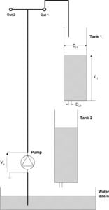
Single Input Single Output (SISO) system
In this setup, the pump feeds directly into the Tank 1, where the liquid level is measured using the pressure sensors. Tank 2 is not used. The objective is to regulate or track the liquid level in the Tank 1.
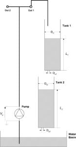
State-coupled SISO system
In this configuration, the pump feeds into the Tank 1, which in turn feeds into the Tank 2. The controller needs to regulate or track the liquid level in the Tank 2 through the voltage applied to the pump.
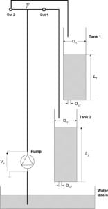
State-coupled and Input-coupled SISO system
Here, the pump feeds into the Tank 1 and Tank 2 using a split flow. Tank 1 also feeds into the Tank 2. The objective is for the controller to regulate or track the liquid level in the Tank 2 by using the pump.
The Coupled Tanks system in Single Input Single Output (SISO),
State-Coupled SISO and State-coupled & Input-coupled SISO configurations.
The ‘disturbance tap’ adds even more flavor to the experiments. It can be used to study the robustness of different control algorithms. You can also change the inlet and outlet orifice diameters to change the flow rate into and out of the tanks, effectively modifying the dynamics of the system.
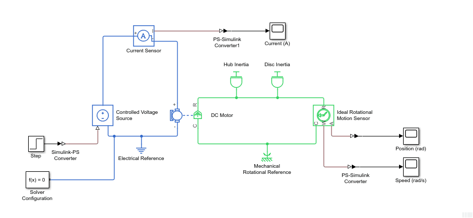
Modeling
The model of the single-tank SISO system can be derived using the Bernoulli principle:
![]()
where c1 and c2 are constants based on the pump flow rate and the cross-sectional area of the inlet and outlet orifices, L1 is the water level in the Tank 1, and Vp is the voltage going to the pump. As the equation shows, this system is nonlinear due to the square root term. This gets more complicated when considering configuration #2 where liquid flows from the Tank 1 into the Tank 2. However, while the system is nonlinear, the equations tend to be more manageable than the equations for a rotary inverted pendulum.
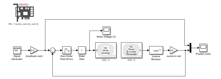
The PID and feed-forward control illustrated below can be used to control the liquid level in the Tank 1 using the pump in this SISO system. The nonlinear equation of motion (EOM) is linearized about the equilibrium point. Using the transfer function, you can derive a set of gains based on time-domain requirements.
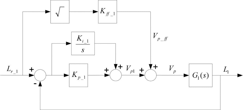
As in the Magnetic Levitation example, the feed-forward control helps improve the response speed. In this case, the feed-forward gain Kff is evaluated at the equilibrium point and is defined by:
![]()
where Lr1 is the water level setpoint of tank 1 and Vp_ff is the voltage of the feed-forward control loop.
To control the liquid level in the Tank 2, you can use two cascading PID loops with a feed-forward element. Thus the control of the liquid level in the Tank 1, derived above, is maintained and an outer-loop is designed to control the liquid level in the Tank 2. The outer-control loop sends the desired, or set point, for the Tank 1 to achieve the desired level in the second tank.
Takeaway
The Coupled Tanks is probably the most versatile system in Quanser’s offering. With the three different configurations, the disturbance tap, and small, medium, and large inlet/outlet orifice diameters, you can have many different dynamics systems. This system can cater to teaching classic control right up to doing research.
Want more?
For more of a challenge, consider the quad-tank system that combines two Coupled Tanks systems together. This system is inherently unstable. See the video of the system in action at:
The researchers from Ghent University and Gheorghe Asachi’ Technical University of Iasi went even further. With the goal to develop control strategies for n-tank systems, they used a sextuple tank setup and worked on the identification method to determine the process model.
Their research paper Modelling and identification of a coupled sextuple water tank system was presented at the 2016 IEEE International Conference on Automation, Quality and Testing, Robotics (AQTR). More recently, they published a paper An industrially relevant formulation of a distributed model predictive control algorithm based on minimal process information in the Journal of Process Control.
Take a look at more research publications using the Quanser Coupled Tanks systems, including those that use quadruple or sextuple tank configurations.