
One common application to autonomous mobile robotics is the idea of line following, which for self-driving cars is expanded to the concept of autonomous lane following. This application can be a starting step into developing a fully autonomous driving example for simulating traffic flow.
Back to Basics
However, before you get to the full autonomy of the vehicle, it’s important to take a step back, and start with basics. In this case, you need to figure out how to keep the car within its lane and follow it.
As part of the mechanical team here at Quanser, I get the opportunity to experiment with some of the leading technologies that are helping researchers along with their exploration. The main tool which allows me to interface and experiment with the hardware is Quanser’s rapid prototyping software called QUARC. Over the past months, I’ve also had the chance to experiment with the QCar platform in a range of different areas such as computer vision, sensor fusion, pose localization, and environment mapping.
QUARC is also in the heart of my QCar’s lane-keeping example I want to talk about. My colleague Murtaza Bohra already explained the thought process behind our QUARC-centric implementation of the lane following application. I highly recommend you read his post Reading Between the Lines for more details. My goal was to develop an even more stable lane keeping algorithm, leveraging MATLAB add-on toolboxes.
Getting Started
My first step in developing the implementation was to identify which portion of my colleague’s application I want to modify. I decided a good starting point would be to focus on the computer vision portion of the application since this gives me the ability to change how the QCar’s heading is modified while keeping the rest of the functionality, such as the speed controller, exactly the same.
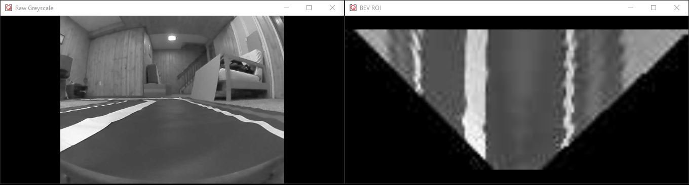
Next, I started investigating alternative methods for interpreting information in an image. This is where I ran into the concept known as image perspectives and the Bird’s Eye View, which is commonly used in autonomous driving applications. Equipped with this information, I was all set and ready to work. I would be modifying the image processing stack by implementing a Bird’s Eye View representation of my forward-facing camera and use this to track the center of my lane. Since the QCar offers a wide range of sensors, in particular vision sensors, I had to decide which one to use for my Bird’s Eye View transform. The QCar is equipped with a front-facing 172-degree FOV CSI camera capable of viewing images at a high refresh rate. For my application, I used the 820×616 resolution with a refresh rate of 80Hz.
To be able to modify the perspective of an image, I needed to be able to define some key parameters which describe my camera. One common method is to use the pinhole camera model to describe the intrinsic for a camera. These include the focal point, principal point, and any sort of radial or tangential distortion that may be present due to the camera lens. This is where using MathWork’s Computer Vision Toolbox became useful. By using a checkerboard, where the length of each square is known, and a set of reference images, I could use the camera calibrator tool to estimate the parameters which define my pinhole model for the camera. This information was useful beyond just my lane following application. By having the CSI camera parameters at my chosen resolution, I could use this information for other applications such as vision-based odometry.
Putting it All Together
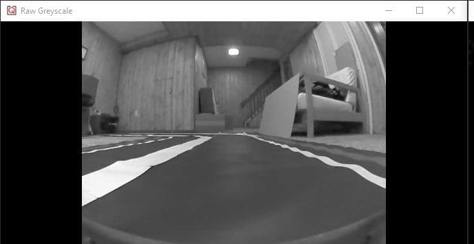
The next step was to transform my input image, i.e., the raw image without any distortion correction, and generate the Bird’s Eye View. Luckily, MathWorks’ Automated Driving Toolbox can transform an input image to a Bird’s Eye View given the camera model parameters of my CSI camera.
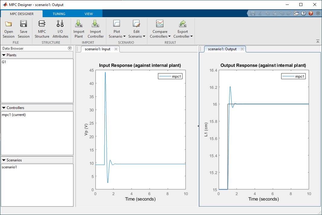
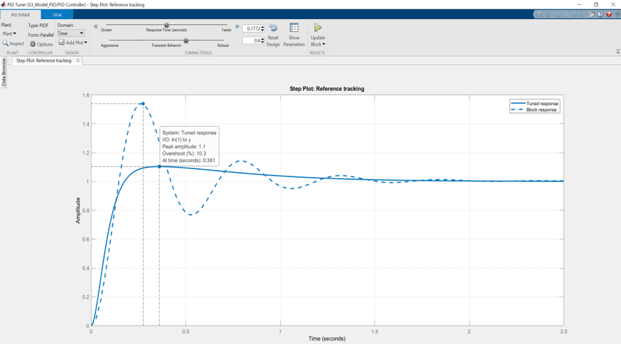
The rest of my implementation involved the use of the QUARC Image Compare blockset to select the areas where the lane is present and a high pass filter to extract the location of lanes. Lastly, the lanes are characterized using a linear polyfit function but the value of interest is their slope since this lets us know in which direction the slope is headed. To maintain the center of the lane as the desired location of the QCar as it travels, a PD controller is implemented to correct for any offset between the center of the lane and the center of the image.
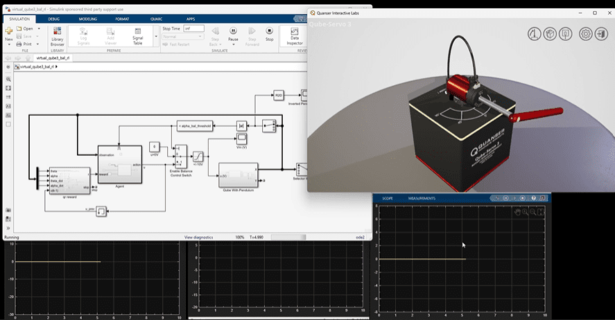
The incredible part of this entire process is that the entire image processing and lane interpretation stack, along with the rest of the control algorithms such as the speed controller, are calculated in real time. If I want to tune the parameters used for the lane-keeping controller or desired speed I can quickly make changes without having to change the code currently running on the QCar. For researchers whose focus is on algorithm implementation and validation, the QCar offers a very flexible platform that can be interfaced with industry-standard packages like the Automated Driving Toolbox.
Where Will You Go?…
Hopefully, by describing the process behind the application development of my QUARC-MathWorks centric example, you can get an idea of how you can easily expand the scope of your research. You are always welcomed to reach out if you have any inquiries about our products. We look forward to seeing the amazing research you perform with our open-architecture solutions!