


So, I hope my last blog post convinced you that pendulums have some serious real-life applications and how they can be used to teach and research important concepts in modelling and control systems. There are different types of pendulum systems and each represent different types of real-world systems and challenges. In this post, I’d like to show you some of common and “not so common” pendulum configurations.
Linear Pendulum or Cart and Pole
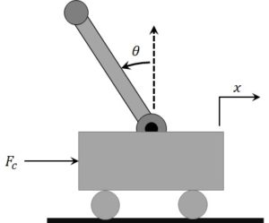
Linear pendulum – also referred to as Cart and Pole – is the most popular configuration showed in dynamic and control systems textbooks. When the pendulum is in the inverted position, the system is unstable, and the cart is used to balance the pendulum. The system is also underactuated because it has only one actuator – the force acting on the cart – and two degrees of freedom – the linear motion of the cart and the rotary motion of the pendulum.
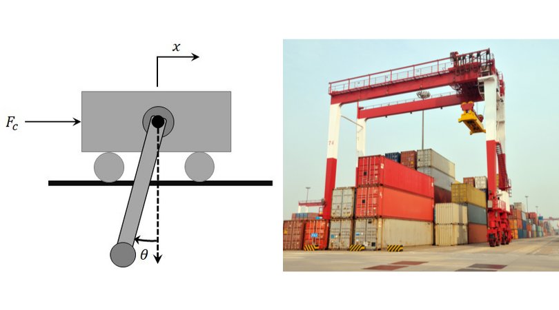
When the pendulum is in the downward configuration, the system can represent a simplified linear gantry crane system. In that case, the control objective is to minimize the motion of the pendulum, i.e., the crane, while moving the cart to a desired position along the track. The free-body diagram of the linear cart and pendulum and an actual linear gantry are illustrated below.
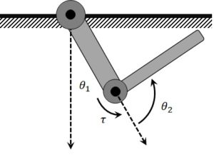
Rotary – or Furuta Pendulum
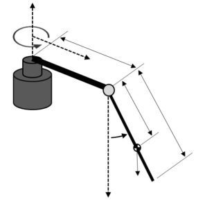 The rotary pendulum system modelling and control design are slightly more involved and challenging compared to the linear inverted pendulum systems. However, one of the advantages of a rotary pendulum system is that it can apply a much larger acceleration at the base of the pendulum, which is beneficial for doing control. Also, if real estate in your lab is at a premium, the rotary pendulum takes up less workspace.
But back to the challenge. Similarly to the linear pendulum, the rotary inverted pendulum is an underactuated system with only one input – the torque applied at the base – and two degrees of freedom – the rotary arm connected to the base and the pendulum at the end. The base is commonly actuated with a rotary DC motor – either direct drive or geared. The rotary pendulum system is often used to balance the pendulum in the inverted position using traditional linear state-feedback control techniques or more elaborate nonlinear control. The pendulum swing-up control is also fairly common, where the objective is to swing the pendulum from the downward configuration to the upward vertical position where the balance control can be engaged.
As with the linear configuration, there are also more challenging versions of the system that includes more links or extra degrees of freedom. The double rotary inverted pendulum is such a system and is typically reserved for advanced teaching or research. Quanser has such a system available, and you can see it in action here:
Pendubot
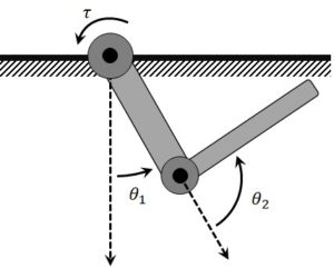 The Pendubot is an underactuated, two-degree of freedom mechanical system that has two revolute, rigid links and a DC motor driving the base joint. The middle joint that is connected to the second link is not actuated.
The Pendubot was widely used by Professor Mark W. Spong and his students. This system is used extensively to design advanced nonlinear controllers and, in particular, swing-up control strategies. It’s typically used to balance or stabilize the second link in the inverted position. There are two modes for this:
- Middle point swing-up: link 1 is in the downward configuration and link 2 balanced in the inverted position
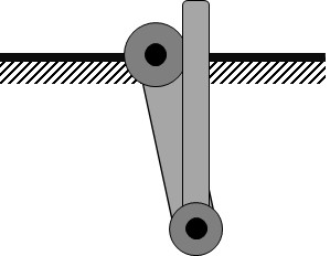
- Top point swing-up: both links are in the inverted position
Designing a successful swing-up controller involves developing an accurate nonlinear model (e.g., using Euler-Lagrange) and knowledge of nonlinear control. The Pendubot has a considerable amount of research papers published, one of the most popular is the energy-based swing-up control design (I. Fantoni, April 2000).
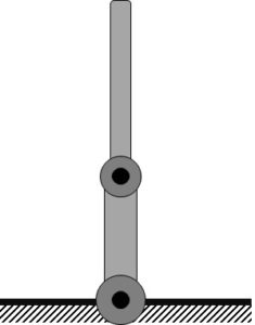
Acrobot
 The Acrobot is similar to the Pendubot system: it’s a two degree of freedom, underactuated mechanical system with two rigid links. However, in this configuration, only the middle joint between links 1 and 2 is actuated (i.e., not the base). Having the middle joint actuated changes the dynamics of the system. One classic paper by Mark W. Spong was the energy-based swing-up control for the Acrobot (Spong M. W., Feb 1995). More recently, the authors in (Marino, 2019) developed an adaptive control for the Acrobot.
Reaction Wheel
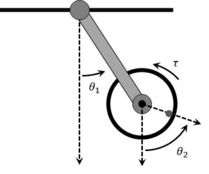
The reaction wheel experiment is another unique pendulum configuration where the actuation point is a DC motor-drive inertial disc located at the end of the link – known as the reaction wheel. The torque generated from the angular acceleration of reaction wheel is used to control the angular position of the pendulum.
The reaction wheel is predominantly used to study swing-up and balance control strategies. While it is seemingly difficult to design such a controller, it can result in a very robust swing-up and balance design. The authors in the (Gil-González, 2019) paper used the reaction wheel pendulum experiment to showcase both classic PID and state-feedback control methods, as well as traditional Lyapunov nonlinear control in a teaching style framework.
Final Remarks
I have outlined several different pendulum configurations here, each with its unique dynamics and control challenges. However, all of them share common traits: they are nonlinear, underactuated, and unstable systems when used in the inverted configuration. These key traits make pendulums one of the most popular experiments in physics, mechanical engineering, and control systems. Here is a summary of what you can do with pendulums in different science and engineering areas:
- Free oscillation response: Find natural frequency and damping. Commonly seen in physics labs and textbooks.
- Nonlinear modelling using either Newtonian physics or Lagrange techniques. Euler-Lagrange is commonly used to model robot manipulators and many other systems.
- Linear modelling: Use the linearization technique to obtain a linear model of the pendulum that is valid about a certain operating point.
- State-space model: Find the nonlinear state equations or linear state-space representation of the linear model.
- CAD Models: Using CAD software tools such as The MathWorks® Simscape Multibody to model the system is another method that can yield highly accurate models of the physical system. See the following link that shows how MathWorks® Simscape Multibody was used to model the Quanser Rotary Inverted Pendulum and design a state-feedback control:
- Linear state-feedback control: Develop a state-feedback control using either the pole placement or optimal control techniques (e.g., LQR).
- Nonlinear control: Lyapunov stability analysis, robust or adaptive control, switching, or hybrid control (for swing-up).
- Observer design: Most of the time, only the angular position of the joints is measured directly (i.e., using an incremental encoder or a potentiometer). The angular rates can be computed numerically by taking the derivative of the measurement and filtering it. However, more accurate estimates of the angular rates can be achieved by designing an observer using techniques such as Kalman filters.
- Fuzzy logic / neural networks: Commonly used to developed non-model based controllers.
- Artificial Intelligence: More recently, AI techniques such as reinforcement learning are being used with pendulums so they can learn how to perform the swing-up and/or balance itself. Read this blog post for more information regarding machine learning.
Hopefully, this sheds some light on why pendulums are popular in engineering teaching and research. They can be used to teach and research a number of very important concepts. In addition, the similarity between their motion dynamics and real-world systems makes pendulums valuable from a “what is this for” standpoint. Therefore, if your next lab, project, or exercise involves a pendulum, rest assured that you will be learning something worthwhile and practical.