

Magnetic levitation technology is used in applications such as contactless photolithography to improve the yield of PCB and microprocessor production. However, magnetic levitation does come with its own set of problems to solve. As discussed in one of our Intermediate Control Systems blog post, the Magnetic Levitation is a very challenging nonlinear system to control.
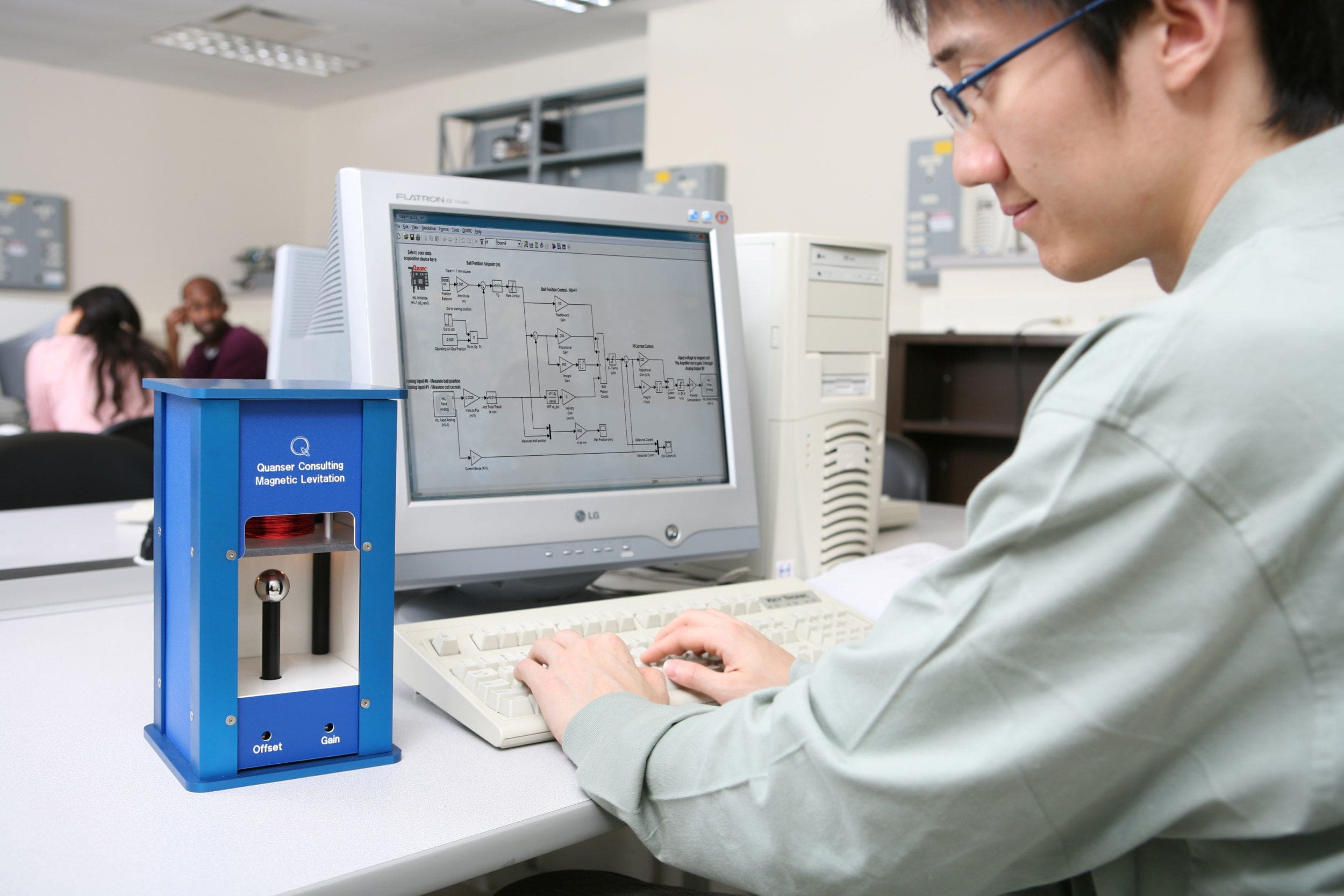
Quanser Magnetic Levitation Experiment
The ball levitation position control system implemented in the Quanser-supplied models for the Magnetic Levitation experiment is a cascade control: an outer loop controls the ball position, and an inner loop controls the electromagnet current. The electromagnet current control is implemented using a PI control, and the ball position is controlled using a PID and feed-forward controller. Based on the desired and measured ball position, the outer ball position control system computes the current required, which is applied to the inner current control.
Professor Vinodh Kumar Elumalai and his team at the Vellore Institute of Technology developed a novel Iterative Learning Control scheme for the Quanser Magnetic Levitation system (Elumalai, 2020).
What’s the basic idea of ILC?
Conventional control systems, such as PID, are based on the dynamic model of the plant. If the model has uncertainties, then the control performance will be degraded. Iterative Learning Control (ILC) is a type of adaptive control strategy that adjusts the control action according to past control efforts and is effective in improving both the trajectory tracking response and the robustness of the system. ILC is a model-free method and is an add-on control used with another feedback control system that provides the basic stabilization, e.g., PID.
What did the authors do?
The Magnetic Levitation system is prone to disturbances and uncertainties. The system is highly nonlinear – the force acting on the ball increases rapidly as the ball approaches the electromagnet. The electromagnetic force also changes over time as the coil heats up (the inductance actually goes up). Further, there is inherent noise in the current and ball position sensors. Incorporating an ILC protocol dynamically adapts to elements that are not modeled and efficiently handled by the PID controller and can, therefore, improve the robustness and trajectory tracking.
The authors implemented a current cycle feedback ILC controller (CCF-ILC) and added it to the existing PID-based control. The following block diagram demonstrates the ILC strategy that the authors have developed:
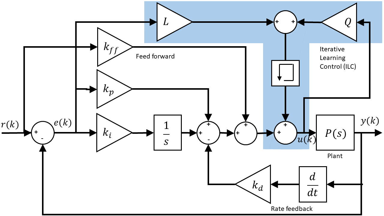
The standard PID and feed-forward (FF) control that is:
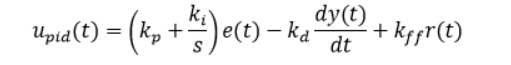
The ILC control component is described by:
![]()
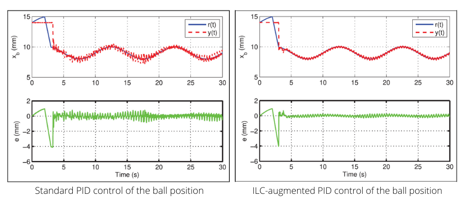
where Q and L are the ILC filter gains, and Fb is the feedback controller. Note how it uses past control signal information. The figures below show the improvement of the ball position response using CCF-ILC scheme over the PID-based control:
This post offers only a brief overview of the work of the researchers at VIT. You can find more details on the protocol developed, stability analysis, disturbance rejection results, and so on in their paper published in the Transactions of the Institute of Measurement and Control journal.