Rotary Flexible Link

Control and vibration analysis of flexible links
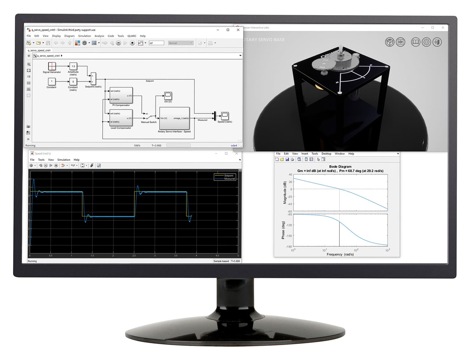
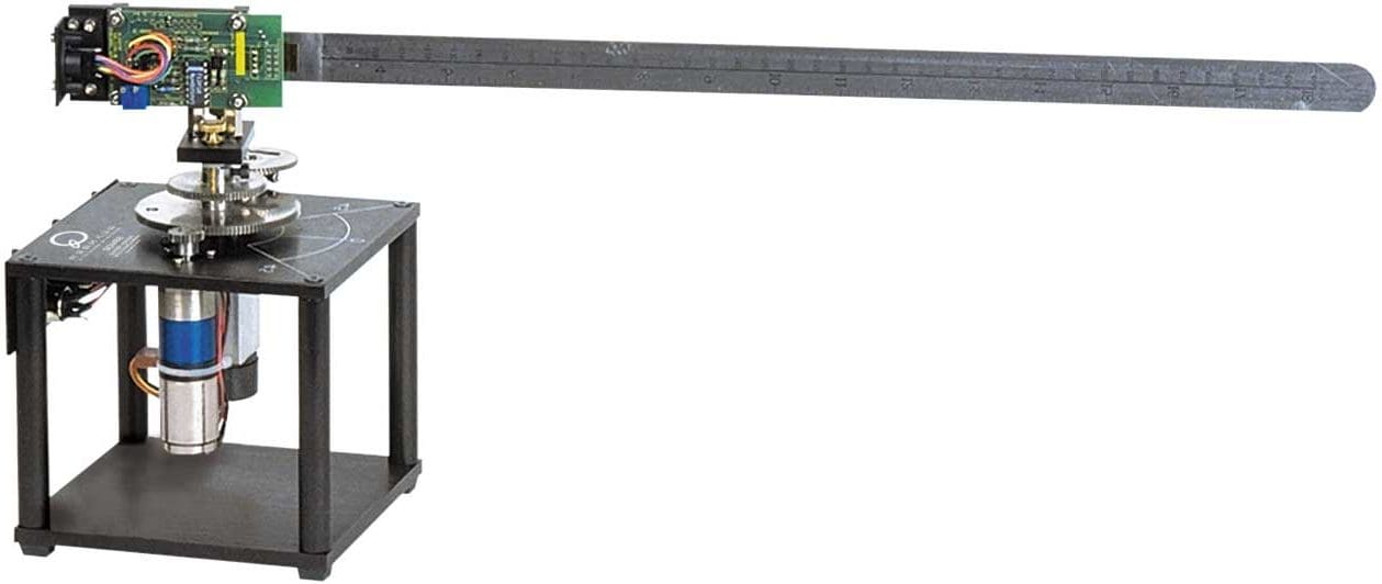
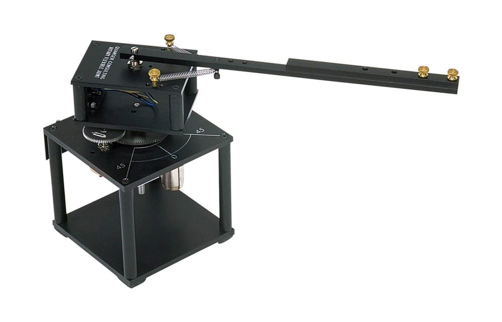
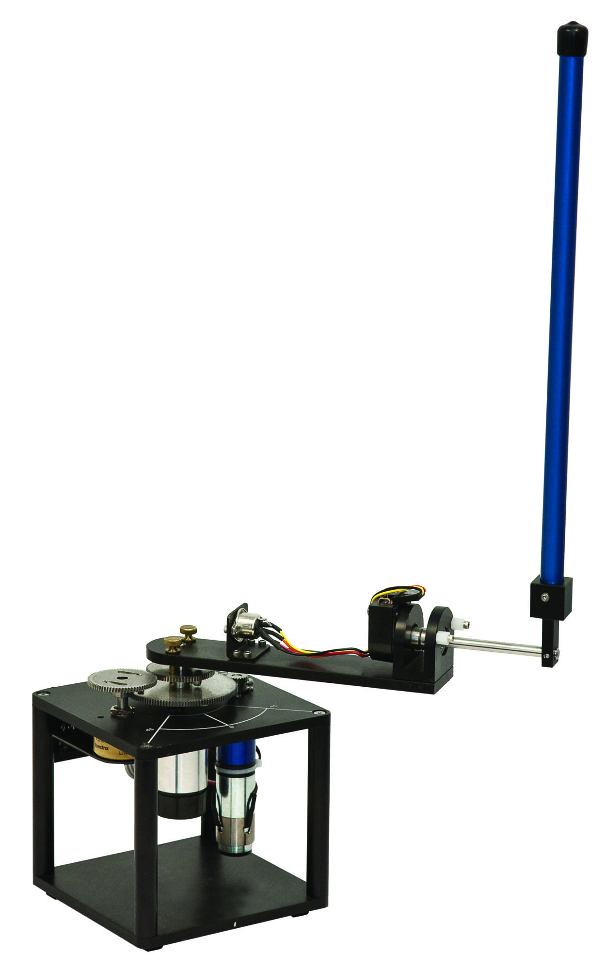
The Rotary Flexible Link module is designed to help students perform flexible link control experiments. The module is designed to be mounted on the Rotary Servo Base Unit. This experiment is ideal for the study of vibration analysis and resonance and allows to mimic real-life control problems encountered in large, lightweight structures that exhibit flexibilities and require feedback control for improved performance. The experiment is also useful when modeling a flexible link on a robot or spacecraft.
Product Details
The Rotary Flexible Link consists of a strain gage which is held at the clamped end of a thin stainless steel flexible link. The DC motor on the Rotary Servo Base Unit is used to rotate the flexible link from one end in the horizontal plane. The motor end of the link is instrumented with a strain gage that can detect the deflection of the tip. The strain gage outputs an analog signal proportional to the deflection of the link. In this experiment, students learn to find the stiffness experimentally, and use Lagrange to develop the system model. This is then used to develop a feedback control using a linear-quadratic regulator, where the tip of a beam tracks a desired command while minimizing link deflection.
- High resolution strain gage to sense link deflection
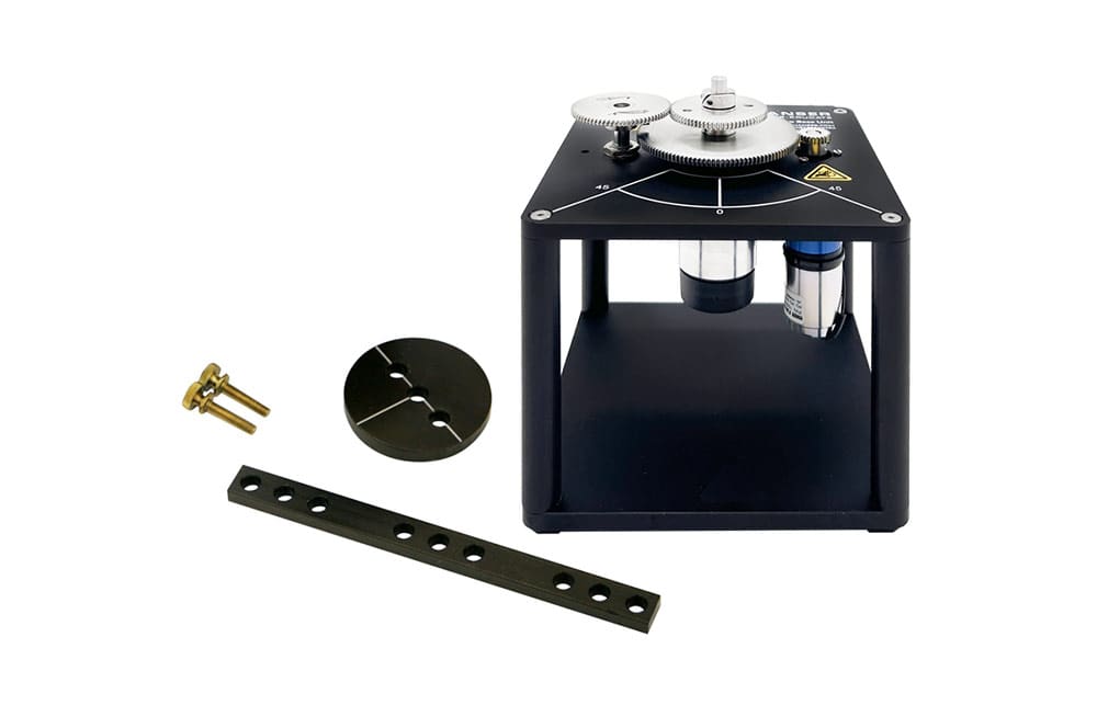
- Flexible Link module easily attaches to the Rotary Servo Base Unit
- High quality aluminum chassis with precision-crafted parts

Modeling Topics
- Lagrange derivation
- State-space representation
- Model validation
- Parameter estimation
Control Topics
- Linear-quadratic regulator
- Vibration control
The following additional components are required to complete your workstation, and are sold separately:
For Simulink
- QUARC® add-on for MATLAB®/Simulink®
- Rotary Servo Base Unit
- Quanser VoltPAQ-X1 linear voltage amplifier
- One of the following DAQ devices:
- Quanser Q2-USB
- Quanser Q8-USB
- Quanser QPIDe
For LabVIEW
- Quanser Rapid Control Prototyping (Q-RCP) Toolkit® add-on for NI LabVIEW™
- Rotary Servo Base Unit
- Quanser VoltPAQ-X1 linear voltage amplifier
- One of the following DAQ devices:
- NI CompactRIO with Quanser Q1-cRIO
- NI myRIO with Quanser Terminal Board
- Quanser Q2-USB
- Quanser Q8-USB
- Quanser QPIDe
Group Citation: Fundamental Control
Explore more: All Research Paper


Related Products
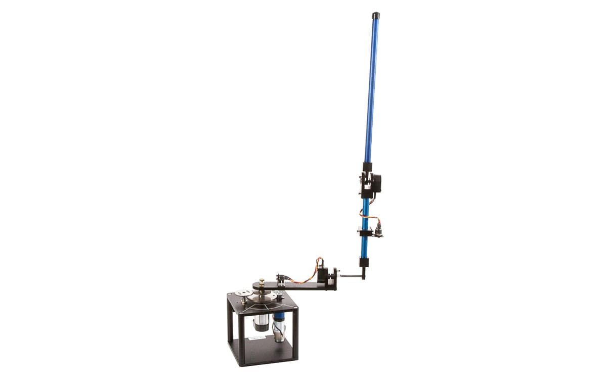
Rotary Double Inverted Pendulum
Take the classic inverted pendulum challenge to the next level
Rotary Flexible Joint
Modeling flexible joints in robotic arms
Rotary Inverted Pendulum
A classic modeling and control systems experiment
Rotary Servo Base Unit
Foundational modular control experiment