Rotary Servo Base Unit

Foundational modular control experiment
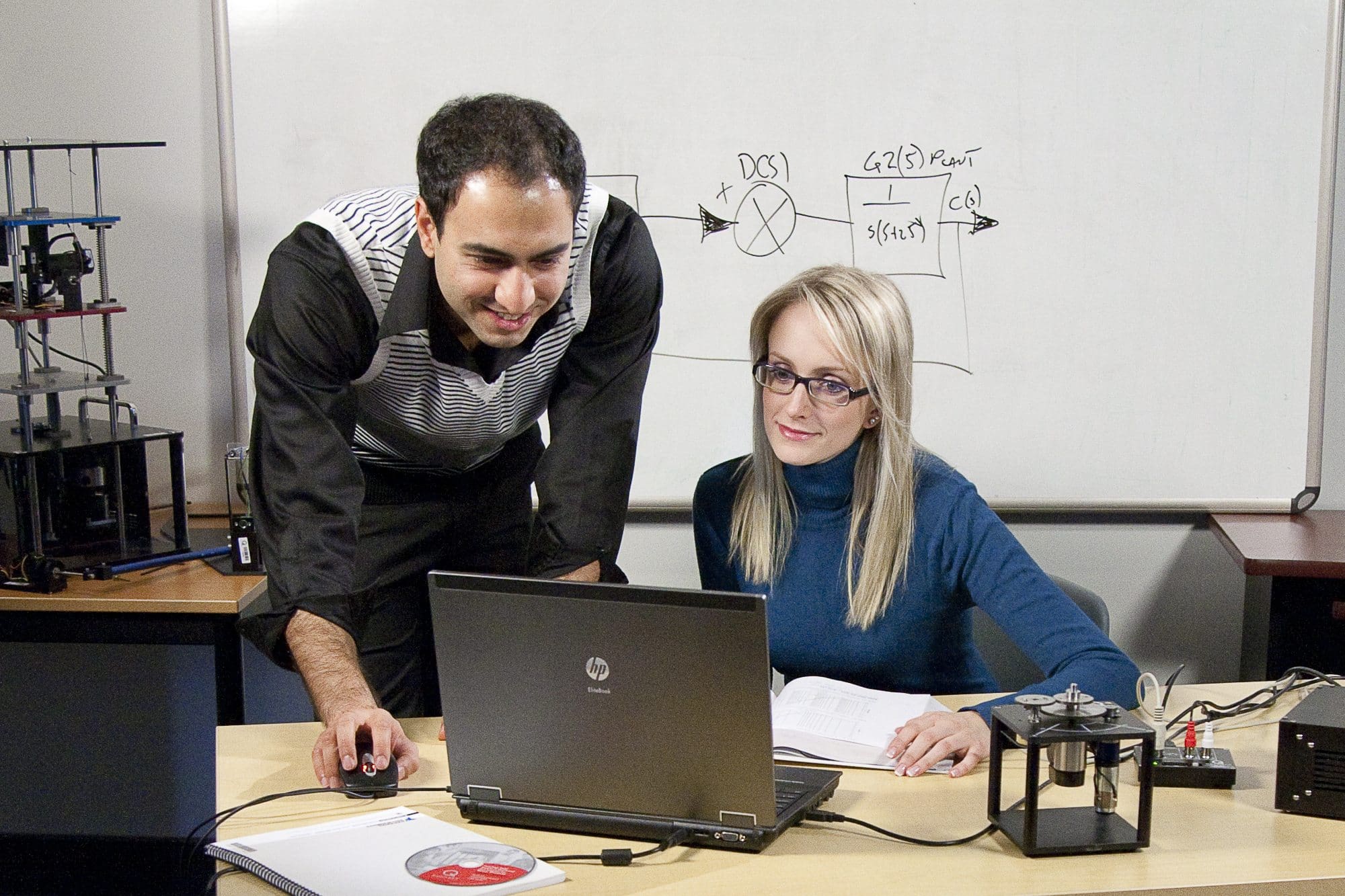
The Rotary Servo Base Unit is the fundamental element of the Quanser Rotary Control family. It is ideally suited to introduce basic control concepts and theories on an easy-to-use and intuitive platform. Use it on its own to perform several experiments or expand the scope of this unit by adding on other modules to teach an even wider range of control concepts. Instructors can thus expose students to a variety of rotary control challenges for a minimal investment. Real-world applications of the rotary servomotor include the autofocus feature in modern cameras, cruise control in automobiles, and servo actuation in aerospace.
Gallery

Product Details
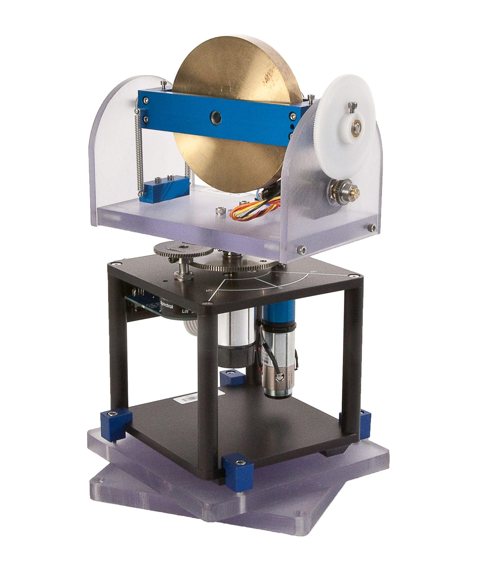
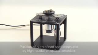
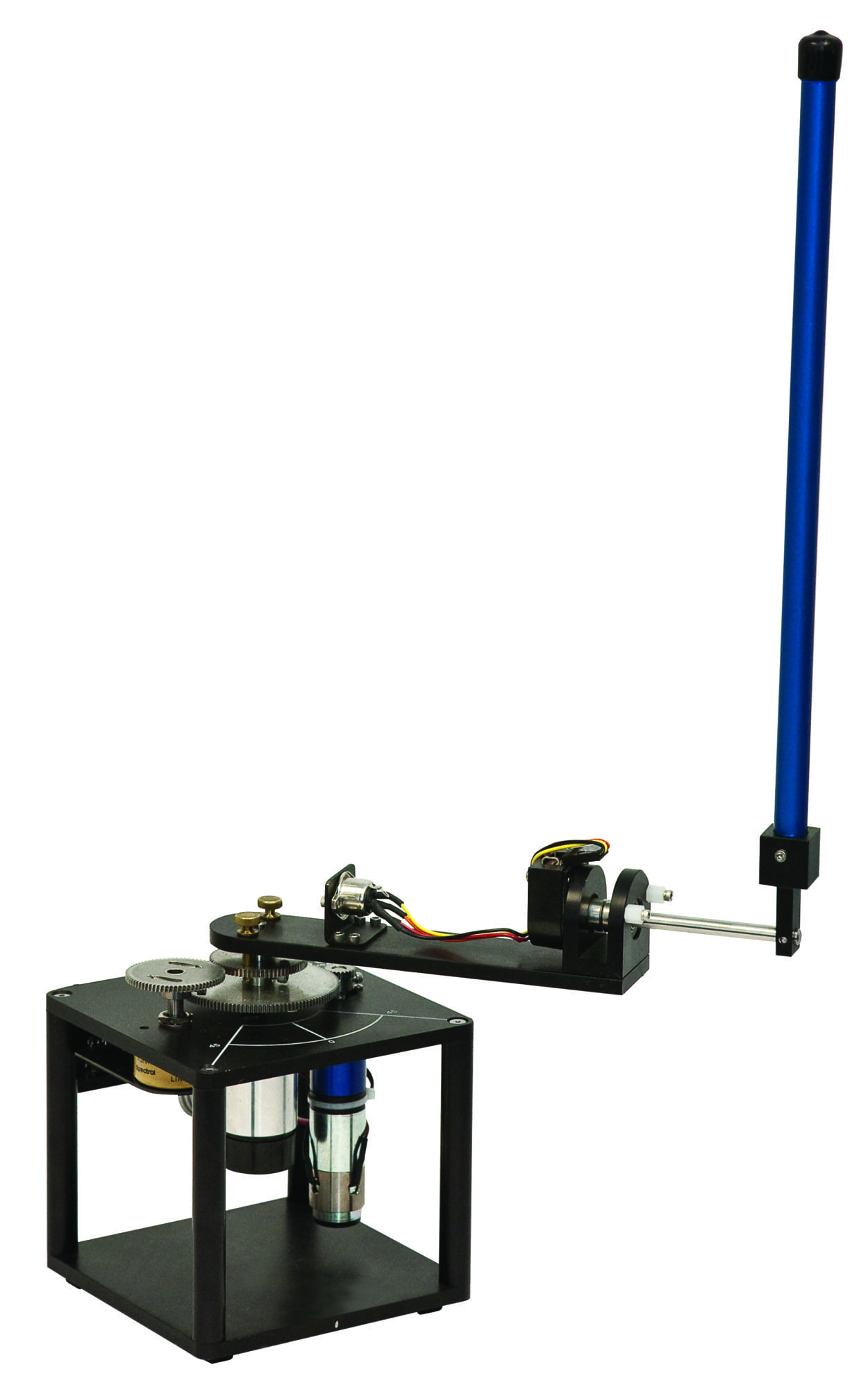
The Rotary Servo Base Unit is a geared servo-mechanism system. The plant consists of a DC motor in a solid aluminum frame. This DC motor drives the smaller pinion gear through an internal gear box. The pinion gear is fixed to a larger middle gear that rotates on the load shaft. The position of the load shaft can be measured using a high resolution optical encoder or a potentiometer. The encoder is also used to estimate the speed of the motor.
- High-quality DC servo motor and gearbox
- High-resolution optical encoder to sense position and estimate motor speed
- Continuous turn potentiometer to sense position
- Variable loads and gear ratios
- Optional slip ring for continuous measurement from instrumented modules
- Ten add-on modules available
| Plant dimensions (L x W x H) | 15 cm x 15 cm x 18 cm |
| Plant Mass | 1.2 kg |
| Motor Nominal Input Voltage | 6 V |
| Motor Maximum Continuous Current (Recommended) | 1A |
| Motor Maximum Speed ( Recommended) | 6,000 RPM |
| Potentiometer Bias Power | +-12 V |
| Potentiometer Measurement Range | +-5 V |
| Encoder Resolution (in quadrature) | 4096 counts/revolution |
Modeling Topics
- First-principles derivation
- Experimental derivation
- Transfer function representation
- Frequency response representation
- Model validation
Control Topics
- PID
- Lead Compensator
The following additional components are required to complete your workstation, and are sold separately:
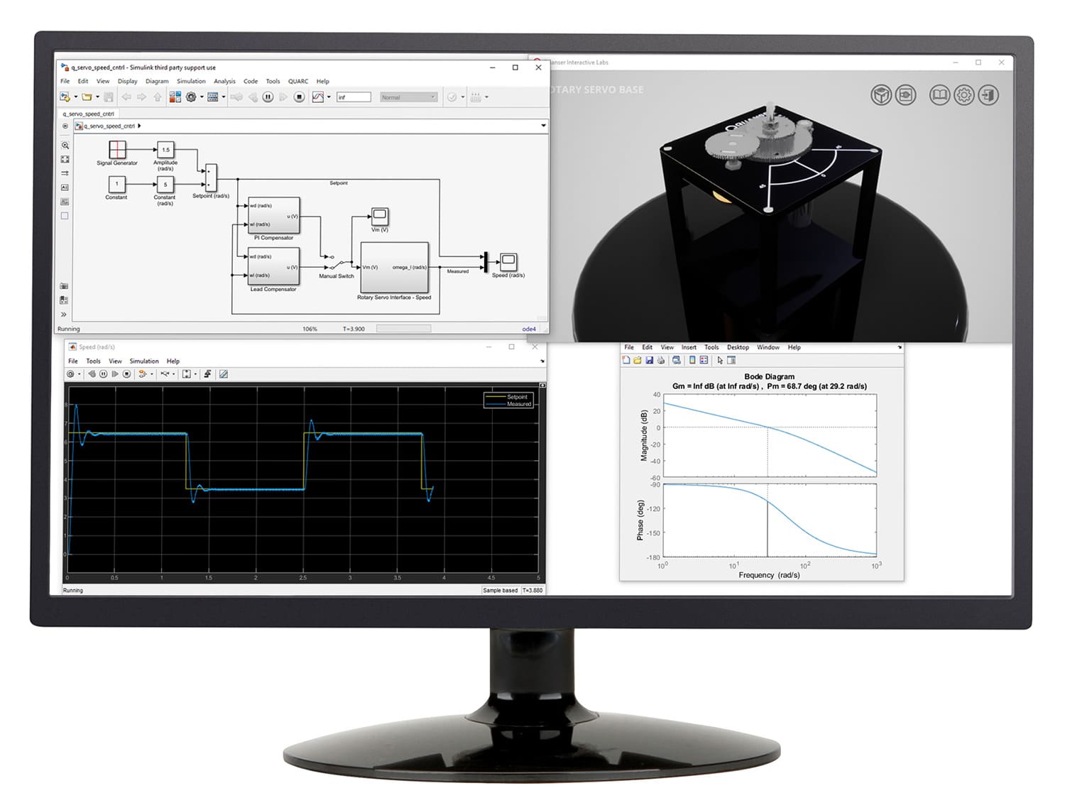
For Simulink
- QUARC® add-on for MATLAB®/Simulink®
- Quanser VoltPAQ-X1 linear voltage amplifier
- One of the following DAQ devices:
- Quanser Q2-USB
- Quanser Q8-USB
- Quanser QPIDe
For LabVIEW
- Quanser Rapid Control Prototyping (Q-RCP) Toolkit® add-on for NI LabVIEW™
- Quanser VoltPAQ-X1 linear voltage amplifier
- One of the following DAQ devices:
- NI CompactRIO with Quanser Q1-cRIO
- NI myRIO with Quanser Terminal Board
- Quanser Q2-USB
- Quanser Q8-USB
- Quanser QPIDe
Group Citation: Fundamental Control
Explore more: All Research Paper
Related Community Resources

Related Products
QLabs Virtual Rotary Servo
Virtual platform for distance and blended undergraduate control systems courses
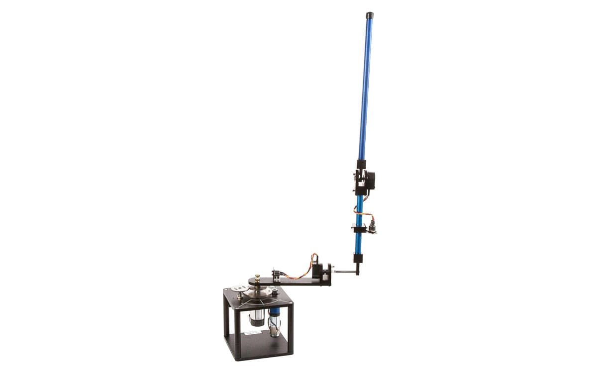
Rotary Inverted Pendulum
A classic modeling and control systems experiment
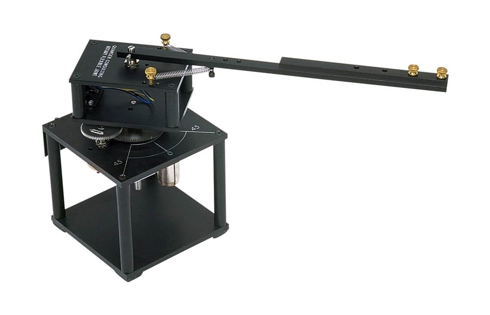
Rotary Flexible Joint
Modeling flexible joints in robotic arms
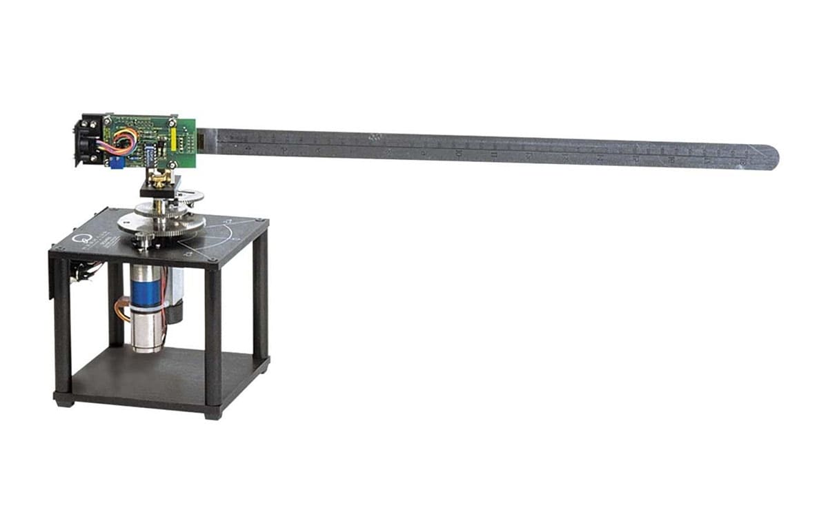
Rotary Flexible Link
Control and vibration analysis of flexible links
Rotary Double Inverted Pendulum
Take the classic inverted pendulum challenge to the next level
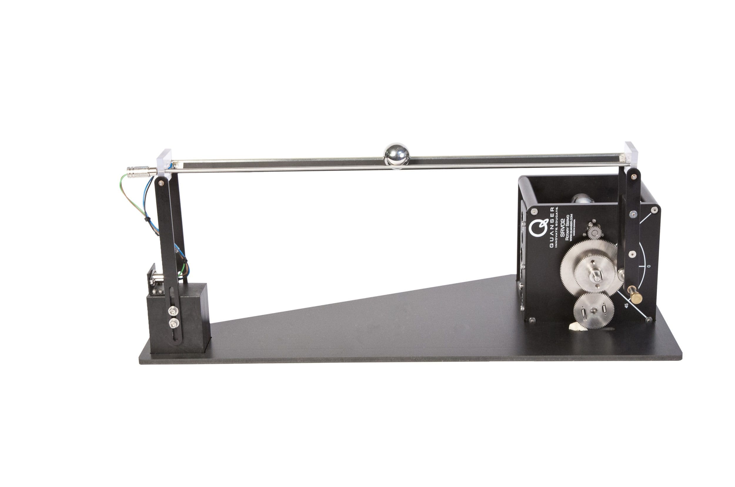
Ball and Beam
Introduce unstable closed loop system control concepts
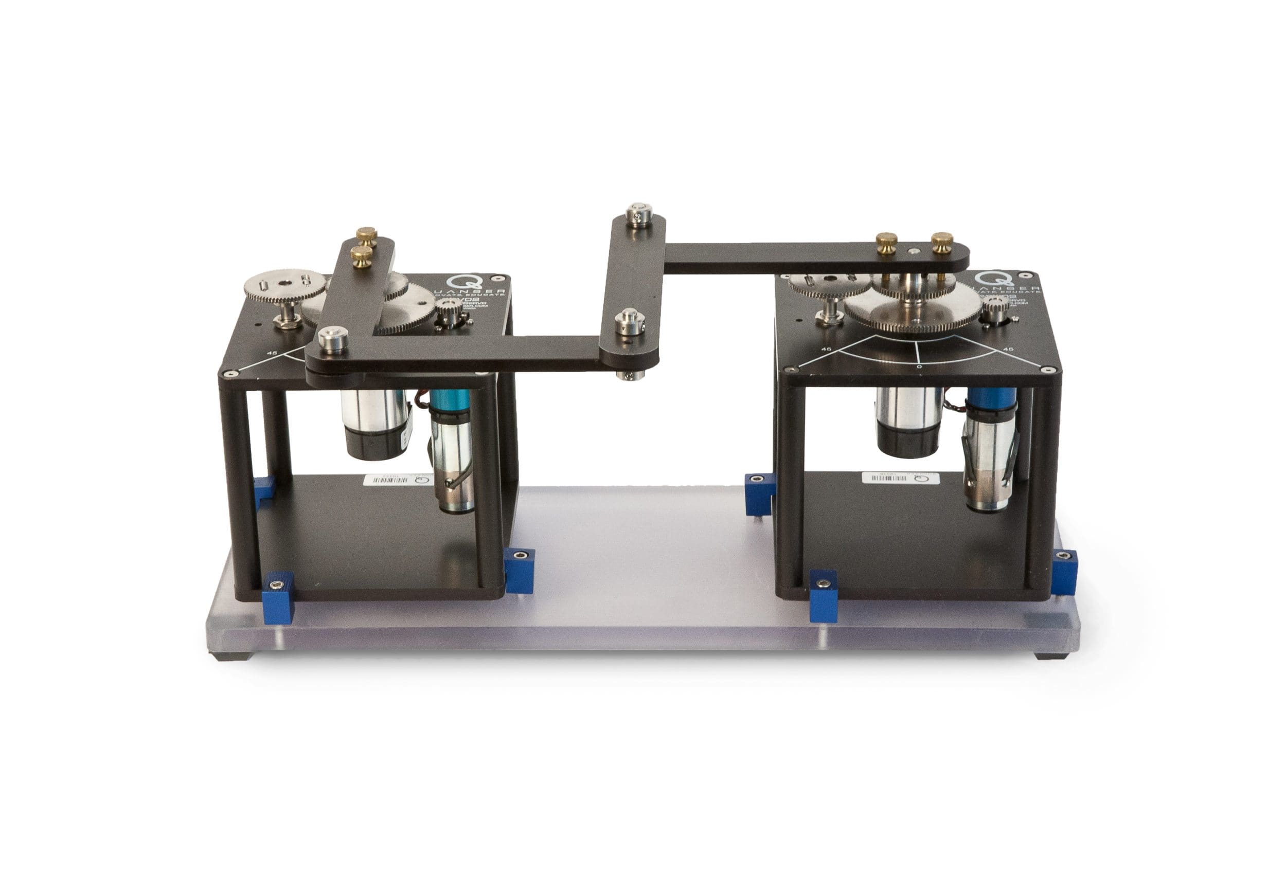
2 DOF Robot
Introduce fundamental principles of robotics
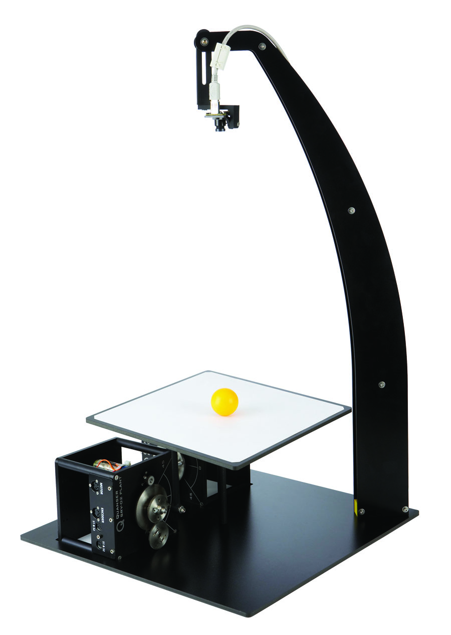
2 DOF Ball Balancer
Introduce vision-based control concepts using the servo family
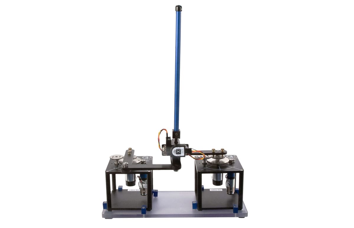
2 DOF Inverted Pendulum/Gantry
Introduce advanced principles of robotics