2 DOF Inverted Pendulum/Gantry

Introduce advanced principles of robotics
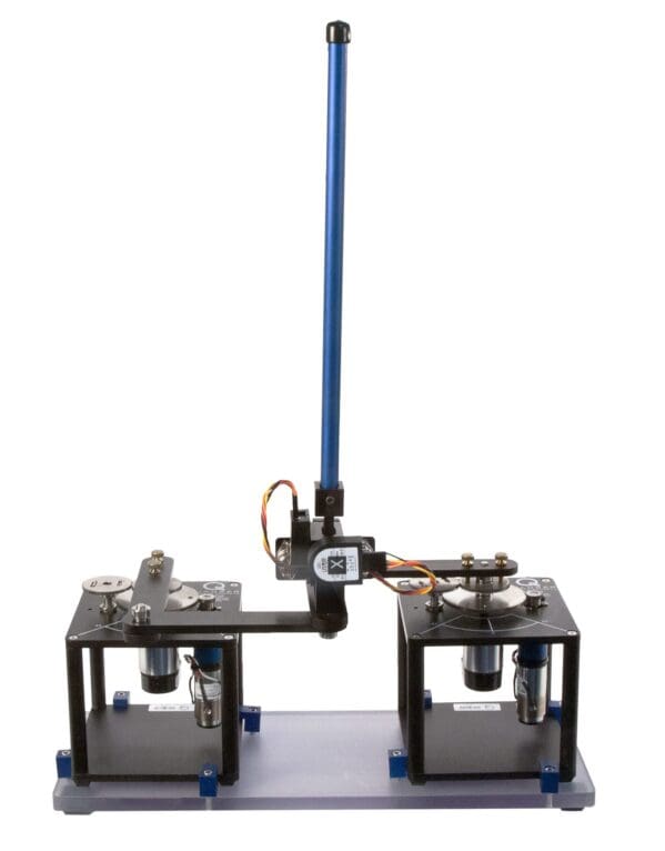
The 2 DOF Inverted Pendulum/Gantry module is ideal to introduce more advanced principles of robotics. You can use it to demonstrate real-world control challenges encountered in aerospace engineering applications, such as rocket stabilization during takeoff.
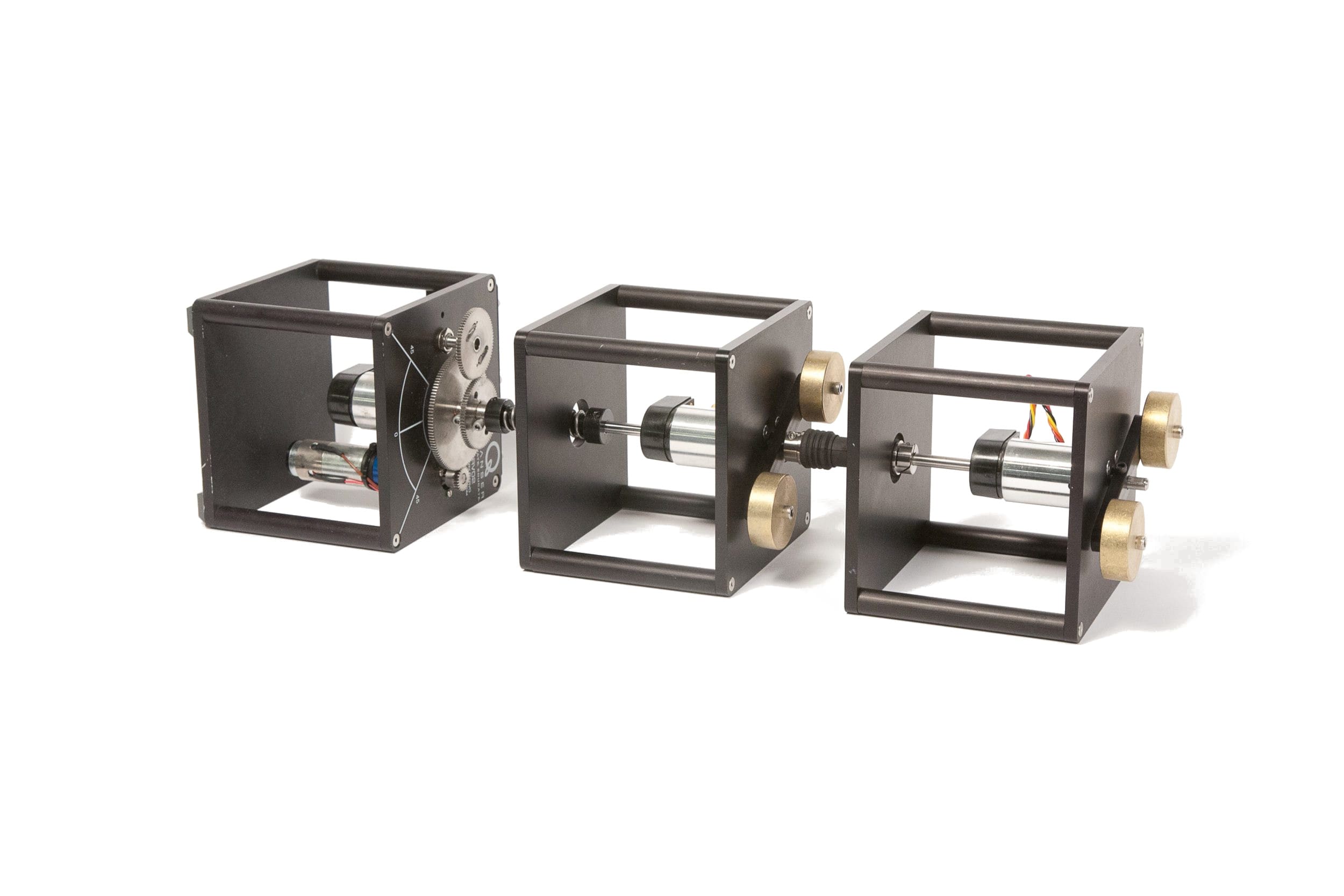
The 2 DOF Inverted Pendulum module attaches to two Rotary Servo Base Units.
Gallery


Product Details
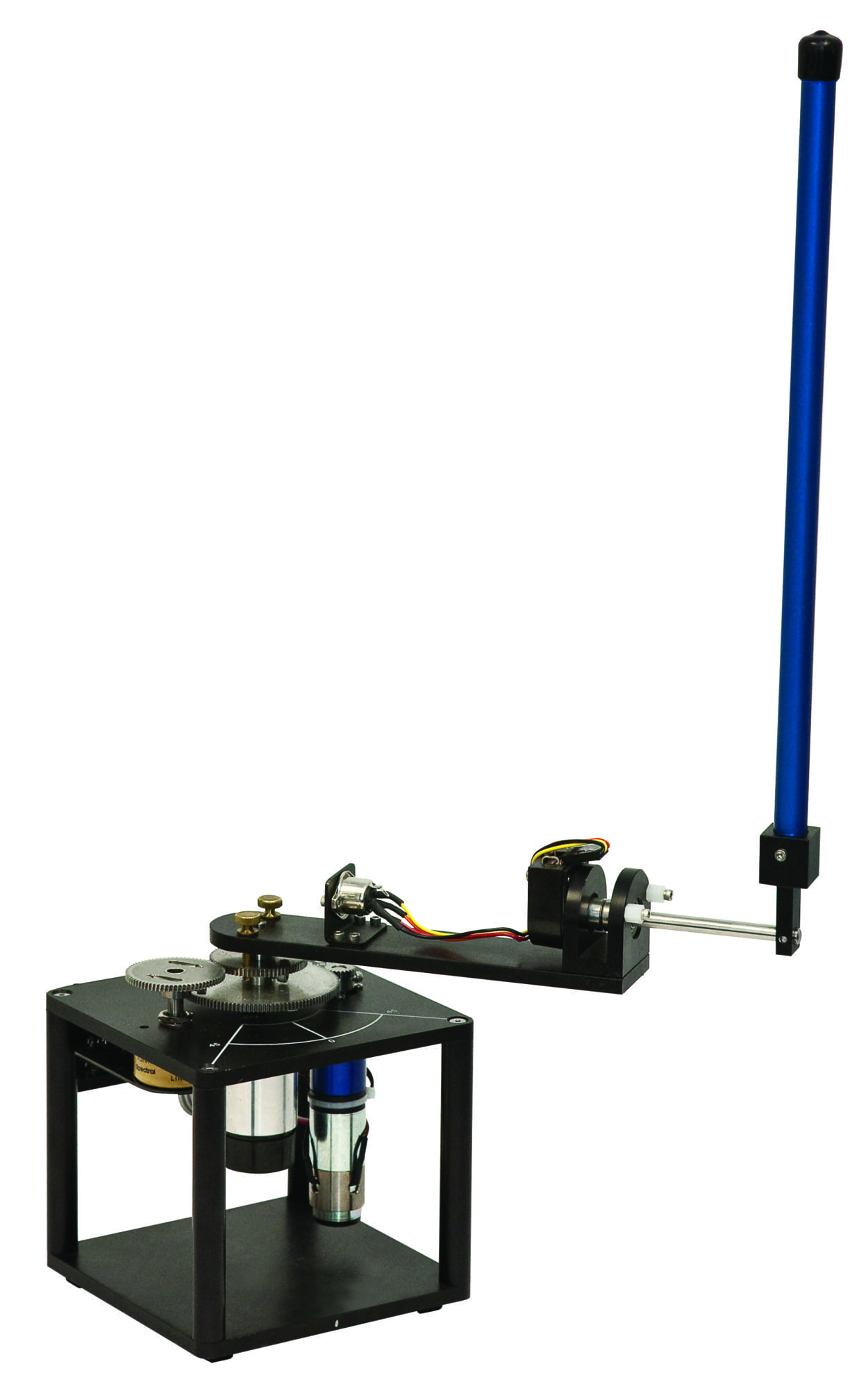
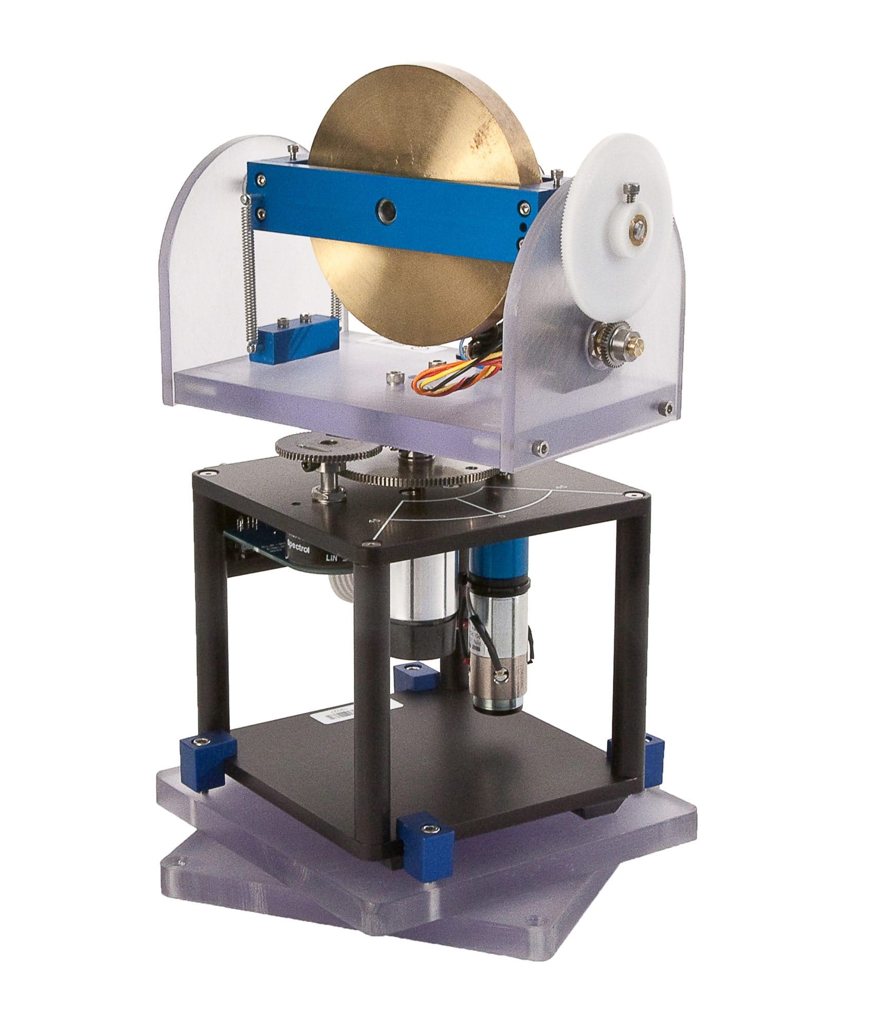
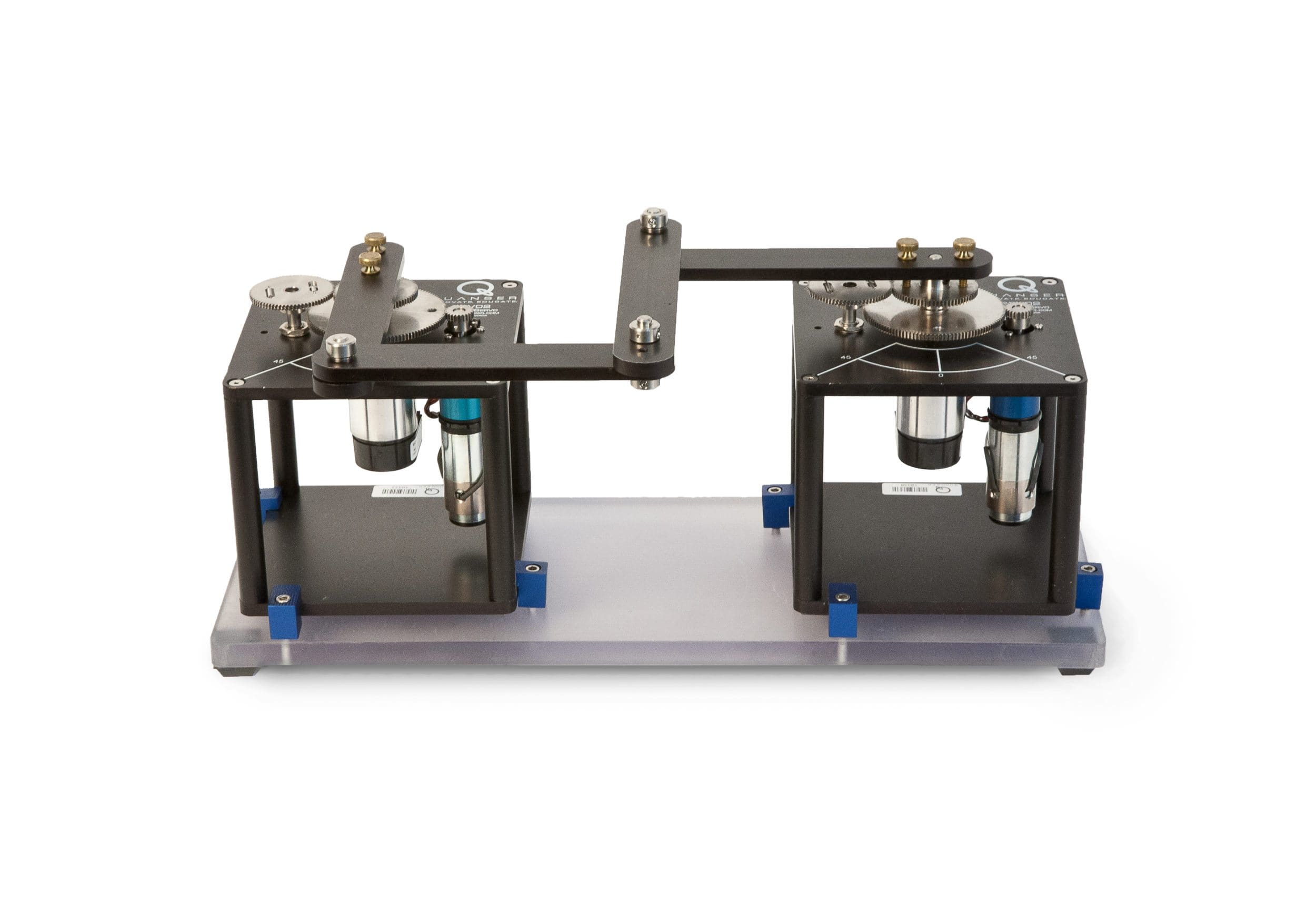
The 2 DOF Inverted Pendulum module consists of an instrumented 2 DOF joint to which a 12-inch rod is mounted. The rod is free to swing about two orthogonal axes. The module is attached to two Rotary Servo Base Units. Their servomotors’ output shafts are coupled through a four-bar linkage, i.e., 2 DOF Robot module, resulting in a planar manipulator robot. The 2 DOF Joint is attached to the end effector of the robot arms.
The goal of the 2 DOF Inverted Pendulum experiment is to command the position of the 2 DOF Robot end effector to balance the pendulum. By measuring the deviations of the vertical pendulum, a controller can be used to rotate the servos, so that the position of the end effector balances the pendulum.
- 2 DOF Inverted Pendulum module easily attaches to the Rotary Servo Base Unit
- Inverted pendulum mounts at the end of the 2 DOF Robot linkage arms
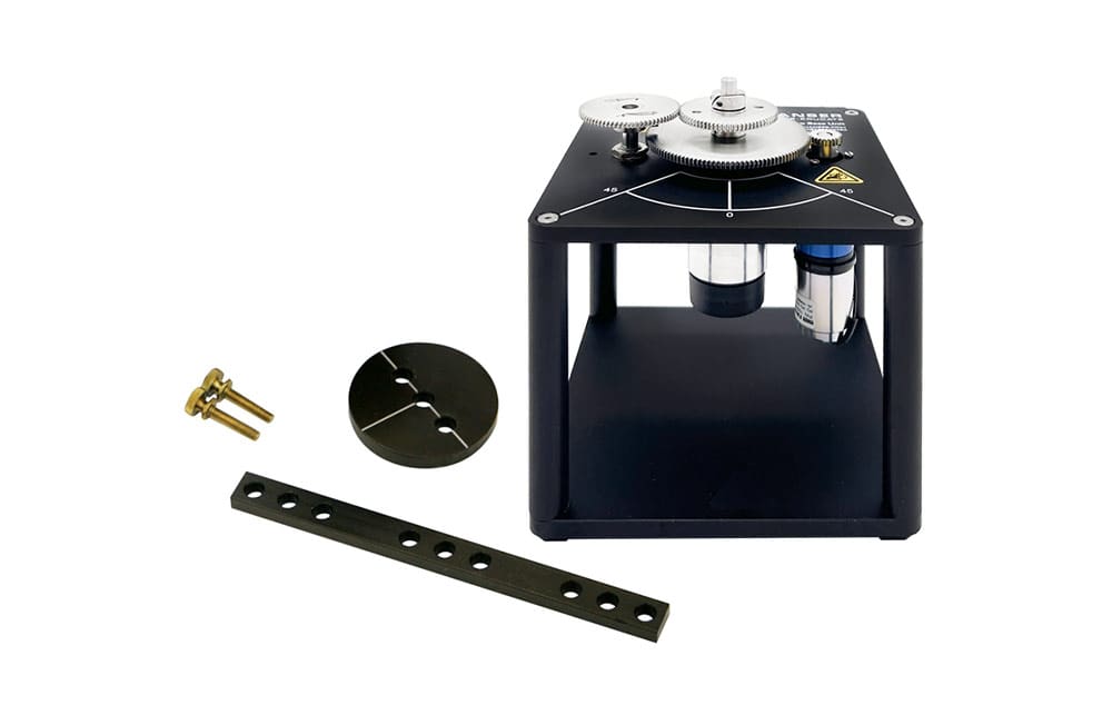
- Configurable for two experiments: 2 DOF Inverted Pendulum and 2 DOF Gantry (pendulum mounts on top or below the linkage arms)
- 2 DOF Joint allows the pendulum to rotate in both orthogonal axes
- High-resolution encoders to sense pendulum link angles
| Mass of 4-Bar Linkage Module | 0.335 kg |
| Mass of Single Link | 0.065 kg |
| Length of a Single Bar in Linkage | 0.127 m |
| Mass of Pendulum (with T-Fitting) | 0.127 kg |
| Mass of 2 DOF Hinge with 2 Encoders | 0.30 kg |
| Full Length of Pendulum (Pivot to Tip) | 0.3365 m |
| Link Moment of Inertia About Cog | 8.74 x 10⁻⁵ kg.m² |
| Link Moment of Inertia About Pivot | 3.49 x 10⁻⁴ kg.m² |
| Encoder Sensitivity on 2 DOF IP Joint | 0.0879 deg/count |
Modeling Topics
- State-space representation
Control Topics
- Linear-quadratic regulator
The following additional components are required to complete your workstation, and are sold separately:
For Simulink
- QUARC® add-on for MATLAB®/Simulink®
- Two Rotary Servo Base Units
- Quanser VoltPAQ-X2 linear voltage amplifier
- One of the following DAQ devices:
- Quanser Q8-USB
- Quanser QPIDe
For LabVIEW
- Quanser Rapid Control Prototyping (Q-RCP) Toolkit® add-on for NI LabVIEW™
- Two Rotary Servo Base Units
- Quanser VoltPAQ-X2 linear voltage amplifier
- One of the following DAQ devices:
- NI CompactRIO with two Quanser Q1-cRIO modules
- NI myRIO with Quanser Terminal Board
- Quanser Q8-USB
- Quanser QPIDe
Group Citation: Fundamental Control
Explore more: All Research Paper
Related Products
Rotary Servo Base Unit
Foundational modular control experiment
Qube-Servo 2
THIS PRODUCT IS NO LONGER AVAILABLE.
Rotary Double Inverted Pendulum
Take the classic inverted pendulum challenge to the next level
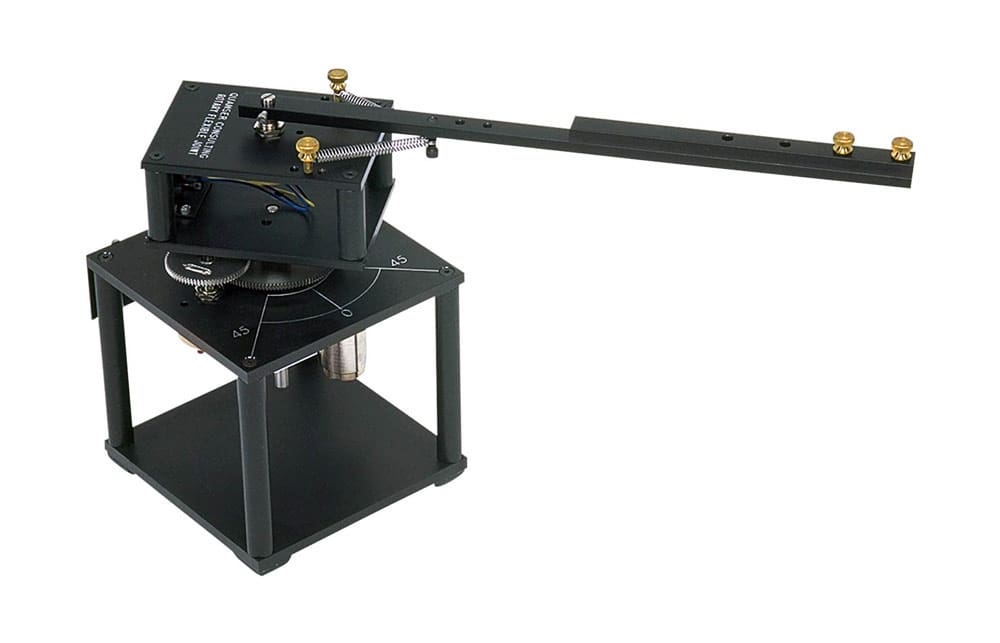
Rotary Flexible Joint
Modeling flexible joints in robotic arms
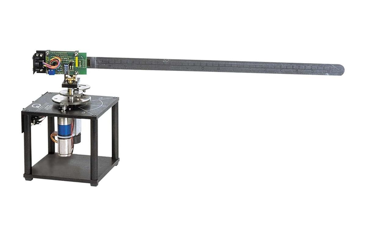
Rotary Flexible Link
Control and vibration analysis of flexible links
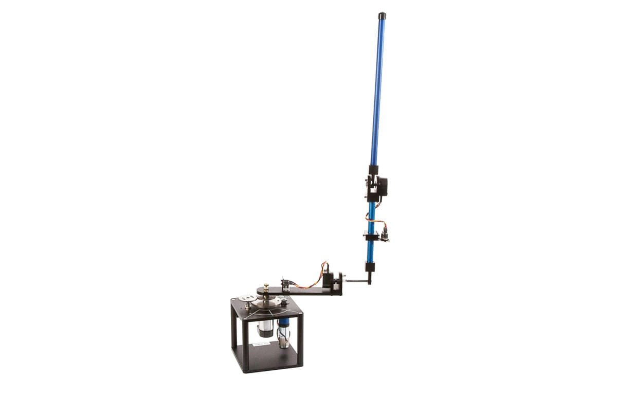
Rotary Inverted Pendulum
A classic modeling and control systems experiment
Multi-DOF Torsion
Multi-dimensional system for torsional dynamics
Gyro/Stable Platform
Introduce rotational dynamics concepts
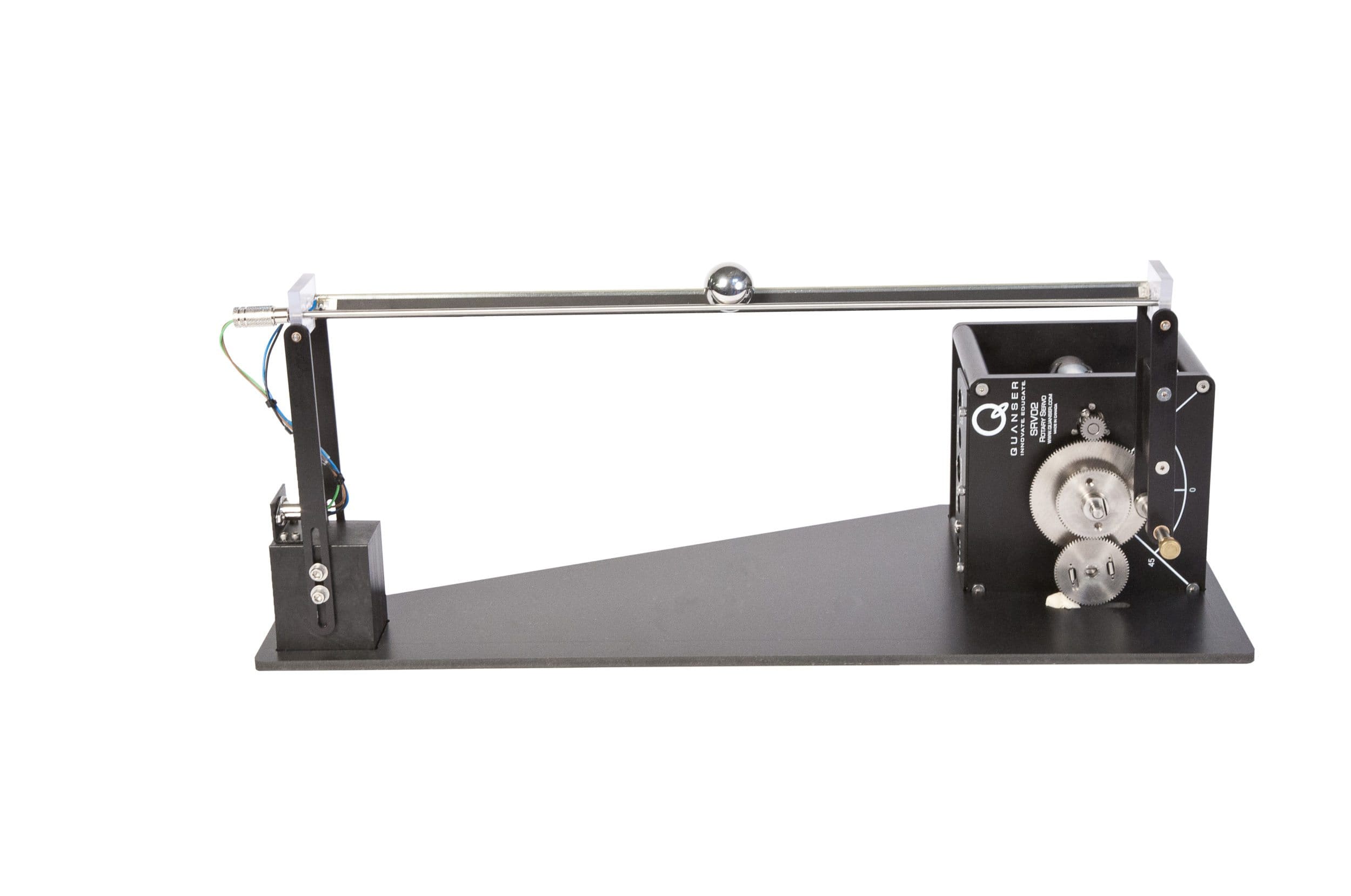
Ball and Beam
Introduce unstable closed loop system control concepts
2 DOF Robot
Introduce fundamental principles of robotics