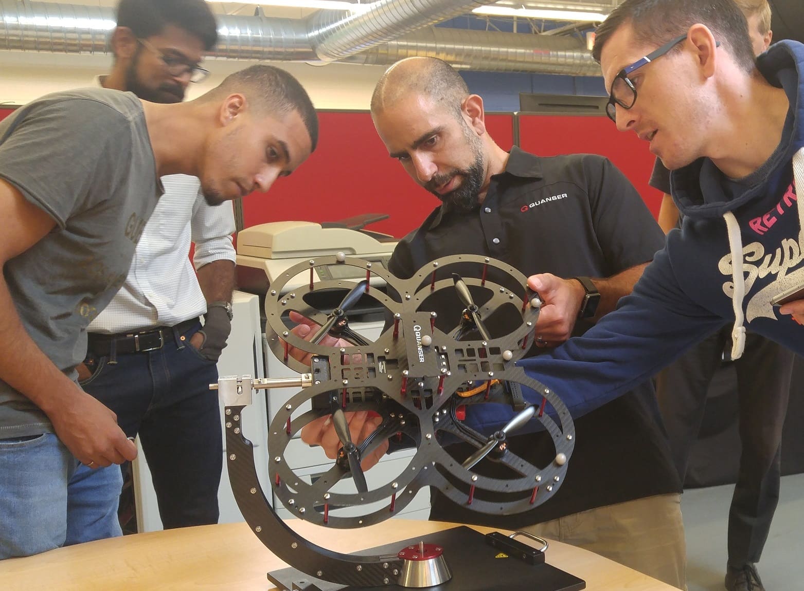

A couple of months ago, I co-authored a whitepaper presenting why thinking (computation) and talking (communication) are two vital tenets of a swarm ecosystem. Furthermore, the whitepaper provided some common approaches to implementing computation as well as communication frameworks within a swarm system. Here is an example of such an application, using Quanser QDrones, the aerial vehicles from the Autonomous Vehicles Research Studio.
The System
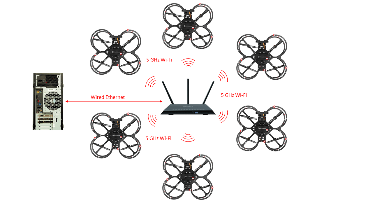
The components of our swarm system include a Ground Control Station (GCS) PC, a router, an Optitrack localization system, and a set of QDrones. The figure below portrays a high-level view of what’s going on. The GCS PC and all the QDrones connect to a router and talk to each other via wireless communication. The GCS PC is running MATLAB/Simulink along with QUARC, Quanser’s Rapid Control Prototyping software. In addition, all the code is developed in Simulink’s standard graphical user-interface.

The Architecture
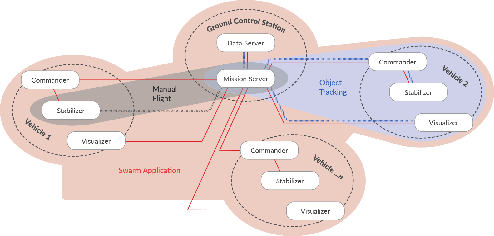
To improve multi-vehicle research efficiency, we identified key functionalities required by researchers for swarm applications and implemented them in the form of Simulink/QUARC subsystems:
- The Stabilizer subsystem provides low-level fast-rate attitude stabilization and read/write access to the QDrone.
- The Commander provides high-level position control and flight safety via a Finite State Machine.
- The Mission Server consists of a user-interface to set desired position commands for any number of vehicles. It also reads localization data from a data server, which gains position estimates from the Optitrack system.
- The Visualizer reads image data from cameras and processes them.
Lastly, a series of blocks serve as a communication wrapper by sending and receiving messages to/from the QDrones and the GCS PC. This is accomplished via a two-way TCP/IP stream server/client setup.
By combining different functionalities, a variety of applications can be developed. The figure below illustrates three applications – manual flight, object tracking and swarm. For the swarm application, I deployed the Commander-Stabilizer subsystems pair on the QDrone with a Mission Server and Data Server running on the GCS PC.
The Swarm
With this setup, we can start combining subsystems to fly the swarm. I placed a Stabilizer and Commander in a single Simulink/QUARC model and placed communication wrapper subsystems around it (stream clients). In a separate Simulink/QUARC model, I placed a Mission Server as well as more communication wrapper subsystems (as stream servers). This established a communication channel between the Mission Server and the Commander-Stabilizer pair. The functionality implemented in the Commander-Stabilizer pair is target-independent. Therefore, I was able to deploy the same piece of code to all six QDrones you see in the video below at the same time and configure the Mission Server to send a uniform 3-dimensional closed-spiral trajectory for the six QDrones.
This swarm architecture is a Lagrangian one, where some computation takes place on the GCS PC (path planning and collision avoidance), and the rest takes place on each QDrone (position control, attitude stabilization and flight monitoring). The actions of each agent are independent of one another. However, a swarm behavior emerges collectively. To implement a Eulerian Swarm, where all the computation takes places on the GCS-PC, deploy the Commander and Mission Server on the PC, (with correctly configured communication wrappers). In addition, deploy the Stabilizer to all the QDrones.
As a result, no matter what your approach to swarms is, this system works, and does so flawlessly (after some testing and fine-tuning, of course). If you have any questions, leave a comment below or email me directly at murtaza.bohra@quanser.com and I’ll touch base with you.
Cheers.