
Some of the most frequently asked questions we get when introducing Quanser systems are “can the user modify the controller?” and “can I access the motor?” The answer to both of them is YES.
One of the main advantages of our systems is that they allow users to directly access the sensors and actuators. That’s what we call “open architecture”. The direct access is enabled through Quanser’s real-time rapid control prototyping software – QUARC for MATLAB/Simulink or QRCP for LabVIEW.
Start with the example Simulink models…
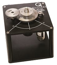 Let’s use the Quanser Rotary Servo as an example. It is one of our flagship and longest standing products. This robust, geared servo system includes a high-quality DC motor and three sensors: rotary optical encoder (incremental), potentiometer, and tachometer.
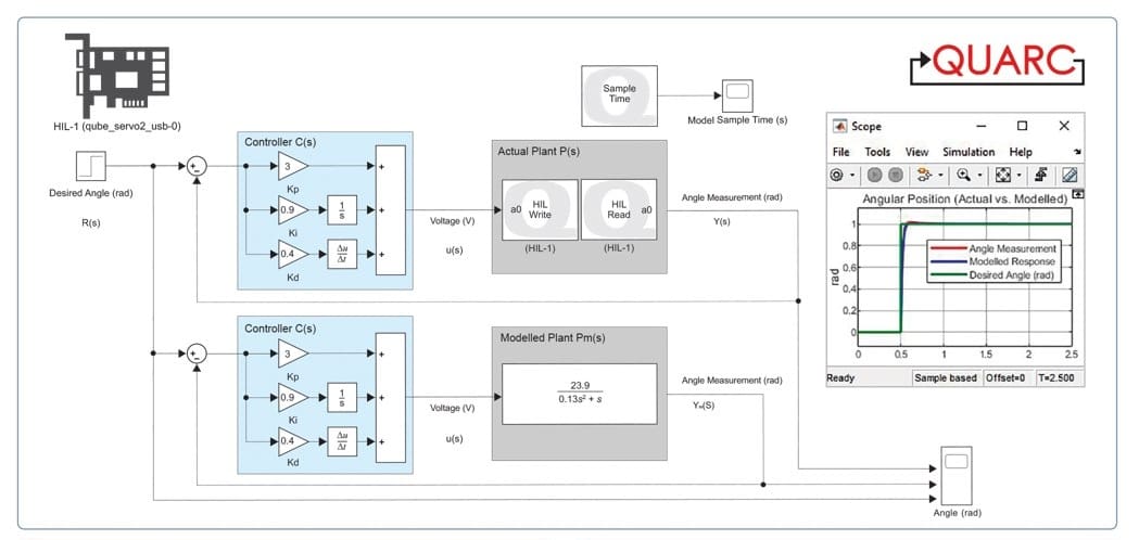
As with all our systems, the Rotary Servo comes with example Simulink models and Matlab scripts. The Simulink model below shows implementation of a Proportional-Derivative (PD) compensator to control the motor position.
The Simulink model uses a combination of standard Simulink blocks, e.g., Derivative, Gain, and Transfer Fcn, and additional blocks from the QUARC Targets library. As I mentioned before, QUARC is Quanser’s rapid control prototyping software. It is easy-to-use, flexible, and extremely powerful real-time RCP software that is seamlessly integrated within the MATLAB/Simulink environment. If you know how to use MATLAB/Simulink, then you already know how to use QUARC.
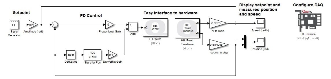 Simulink model using QUARC blocks to implement a PD-based position control of the Quanser Rotary Servo Base Unit
The core QUARC blocks for hardware interface are: HIL Initialize, HIL Read, and HIL Write. These three blocks enable the user to read/write to all the input and output channels on the data acquisition (DAQ) device and, therefore, the actuators and sensors of the system.
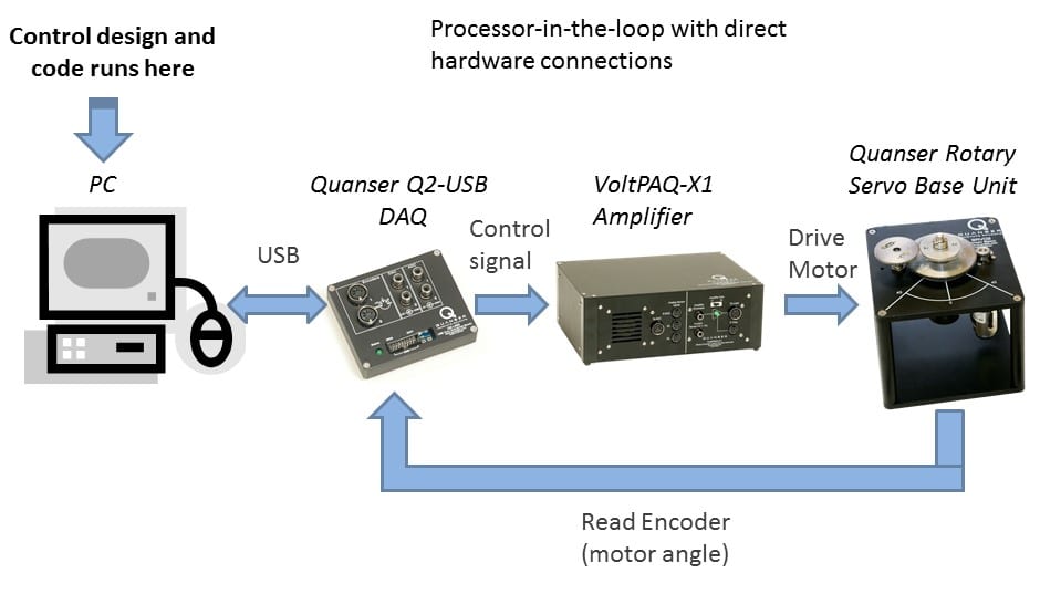
In this case, the HIL Read Timebase block is set up to read the speed of the servo with its tachometer on Analog Input (A/D) #0 and the position of the load gear using its encoder on Encoder Input #0. The PD control calculate a voltage based on the error between the setpoint (i.e. the desired position) and the measured encoder-based position. The PD control voltage is applied to the servo DC motor using Analog Output (D/A) #0 through the connected power amplifier. This is all done through the Quanser Q2-USB Data-Acquisition (DAQ) Device, which is configured using the HIL Initialize block. The illustration below shows how the different systems in the workstation interact with each other.
…then create your own Simulink models
Our open architecture approach to design of Quanser system means that the example Simulink models can be modified. For example, if you want to implement a robust control system such as Sliding Mode with an observer, then the diagram could look something like this:
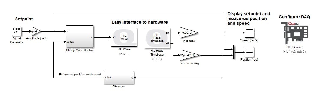
A Simulink model for implementing a sliding mode control with an observer
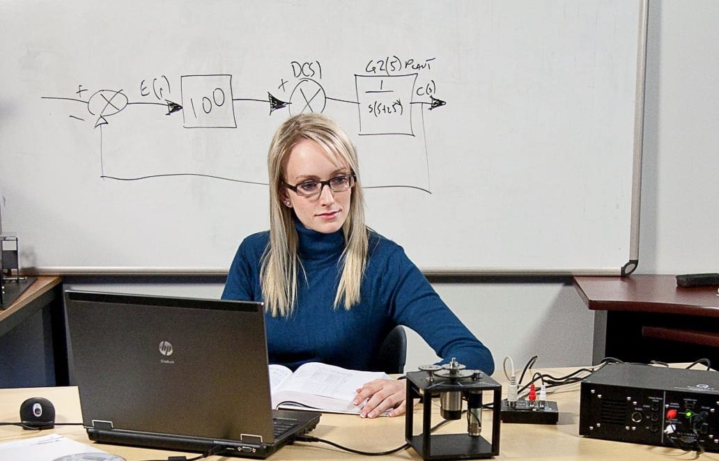
You can also create a completely new Simulink models and interact with the experimental system. Having direct access to the hardware and the powerful software tools is extremely useful in research. In fact, the open architecture design and our real-time rapid control prototyping software are the main reasons why Quanser systems became the de-facto standard validation platforms for researchers. See more than 1,350 research papers listed on our website for examples. You can also read more in our whitepaper The Quanser Platform for Control Systems Research Validation.