
The Quanser Rotary Flexible Link, is a two-degree of freedom system with an actuated rotary servo and a flexible link. It emulates various real-world applications such as lightweight robot manipulators (e.g., in space applications) and cantilever beams. Pictured below, it is and add-on module to the Quanser Rotary Servo Base Unit.

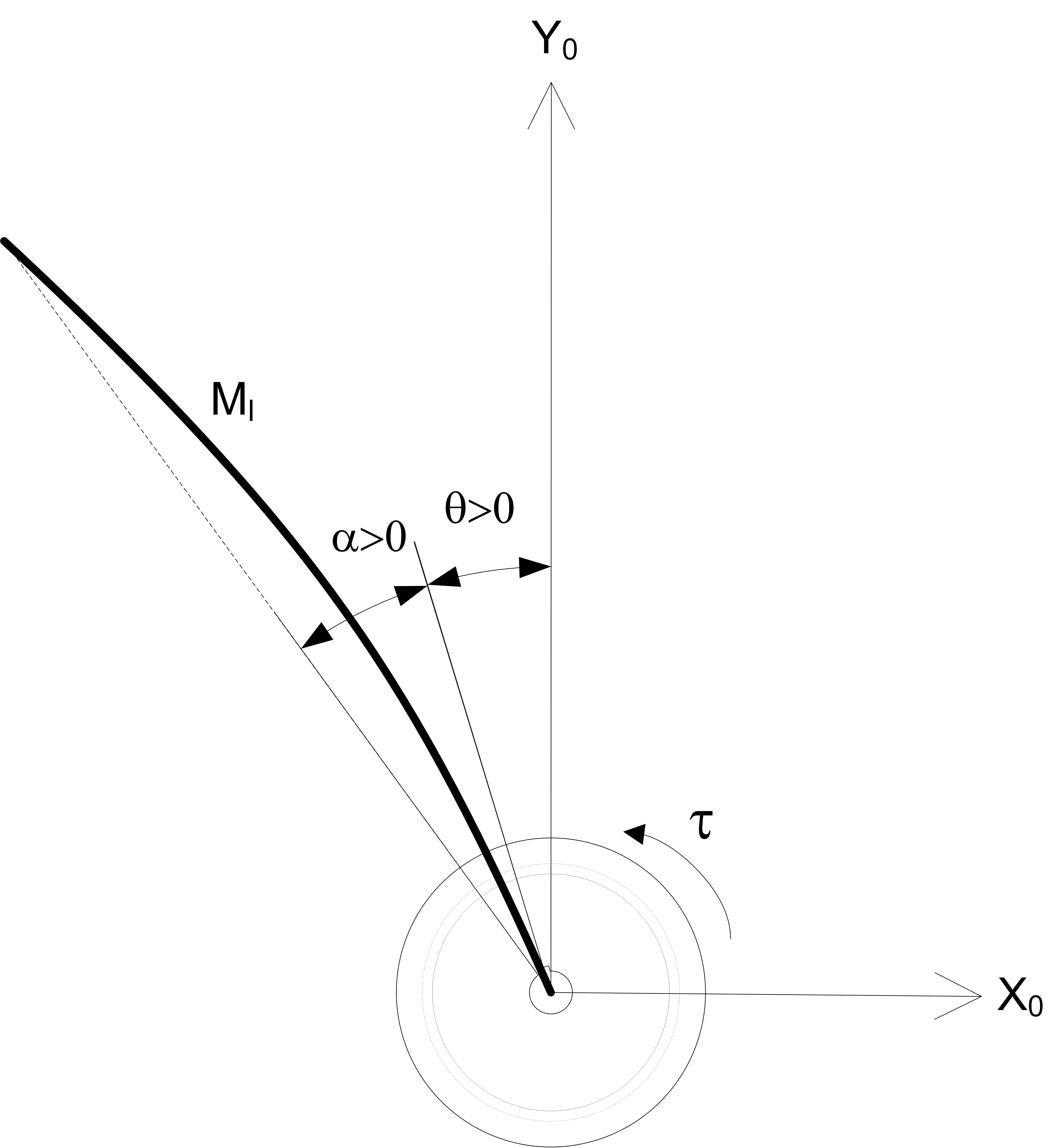
The rotary servo base angle is measured using an incremental encoder, Θ, and the deflection of the flexible link, relative to the servo, is measured using a strain gage, denoted by α.
In this blog, I will show how to use the MathWorks System Identification Toolbox™ to identify the state-space model of a Quanser Rotary Flexible Link. The identified model is then used to design a Linear Quadratic Regular (LQR) based state-feedback controller using the Control Systems Toolbox™. The objective is to design a controller that will:
- Control the position of the servo to a desired angle, and
- Minimize the deflection of the flexible link (as the servo changes positions).
The closed-loop response is tested on both the QLabs Virtual Rotary Flexible Link and the Rotary Flexible Link hardware.
System Identification
Before running the system identification, make sure the Rotary Flexible Link is setup properly. Here are some general guidelines:
- Ensure there are no obstructions.
- Start when the flexible link is motionless, i.e., not vibrating.
- Make sure the strain gage cable is not pulling on the flexible link. This adds a disturbance and can generate a less accurate model.
The following Simulink model is used with the QUARC Real-Time Control Software to apply a square wave voltage to the servo motor and measure the response of the servo angle and the flexible link. The HIL Write Analog block applies a voltage to the DC motor and the HIL Read Timebase block measures the encoder and the strain gage through the Quanser Q2-USB data acquisition (DAQ) device.
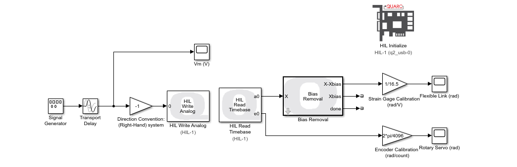
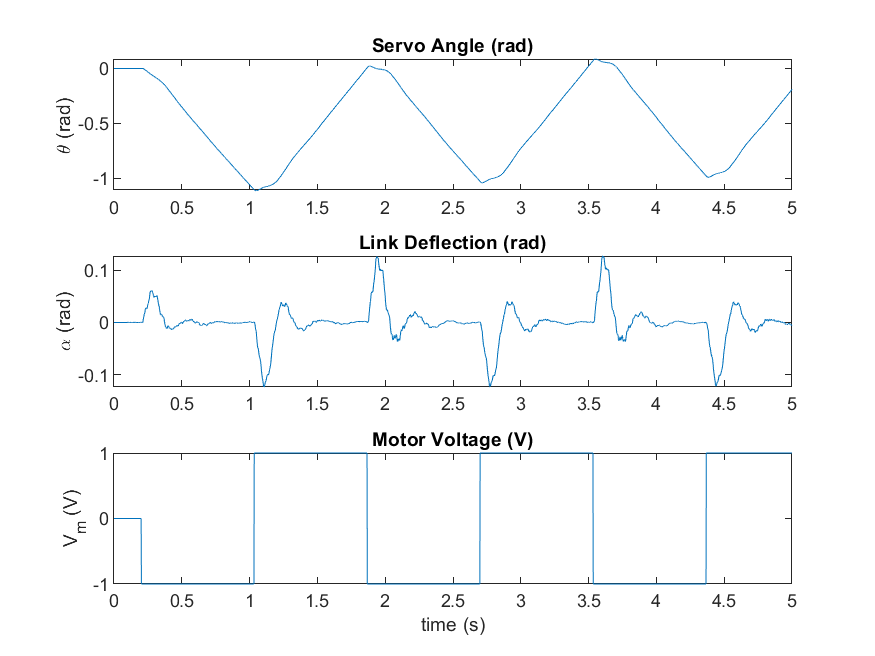
The QUARC Bias Removal block removes any initial offset in the strain gage measurement. The voltage input, servo angle, and flexible link angle are logged and saved as MATLAB variables. The measured open-loop response is shown below.
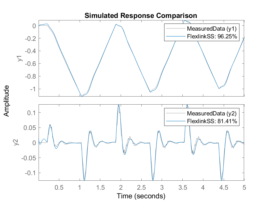
The state-space model is identified using the System Identification Toolbox command ssest. The identified model is validated against the measured results using the compare command.
MeasuredData = iddata([theta,alpha],u,0.002);
[FlexlinkSS, IC] = ssest(MeasuredData,4);
compare(FlexlinkSS,MeasuredData);
As shown by the results in the plot generated by the compare command, the identified state-space model is quite accurate.
Note that there are many other methods and types of models that can be used in the System Identification Toolbox. The continuous state-space model identification used here is “free form”. It did not impose any constraints to the coefficients in A, B, C, and D.
LQR Control Design and Closed-Loop Simulation
Assuming all the states are known we can design an optimal Linear Quadratic Regular (LQR) based state-feedback control to:
- Control the position of the servo to a desired setpoint angle, Θd, and
- Minimize the residual oscillations of the flexible link (e.g., as the servo changes positions).
The full-state feedback control of the Rotary Flexible Link is shown by the following diagram.
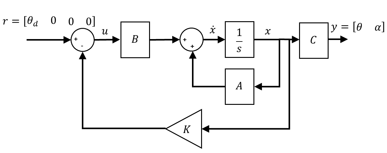
The controller can be defined as:
![]()
The LQR is designed using the MATLAB LQR command using the identified state-space model and by tuning the Q and R weighting matrices.
% Save the identified state-space model as a standard MATLAB state-space
% system
sys_ol = ss(FlexlinkSS);
% Set Q and R LQR weighting matrices
Q = diag([500 0 0 2]);
R = 1;
% Generate feedback control gain using LQR
K = lqr(sys_ol,Q,R);
% Simulate the response in the Simulink model using the identified ss model
open("s_flexgage_control.slx");
sim("s_flexgage_control.slx");
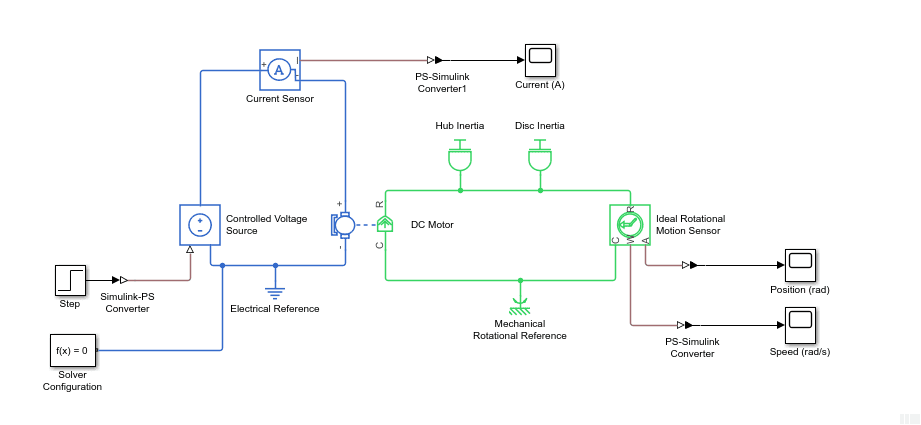
The following Simulink model is used to simulate the closed-loop system. The Simulink State-Space Model block includes the identified model.
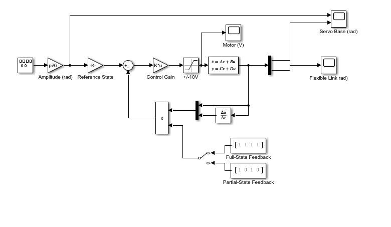
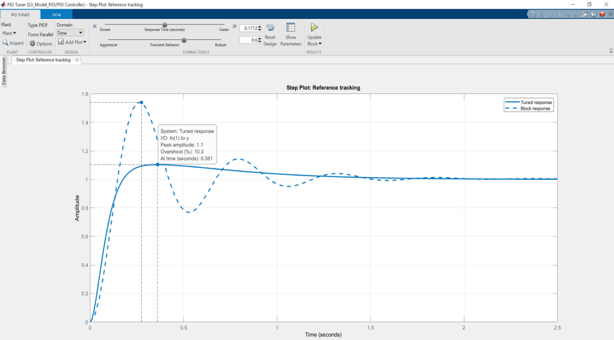
The LQR control design process is iterative. The Q and R weighting matrices are tuned to obtain a response that will yield our objectives of controlling the rotary servo angle to a specific command while minimize the deflection of the flexible link. The motor voltage is also monitored to be within +/- 10 V range. Here is a sample response after going through the design.
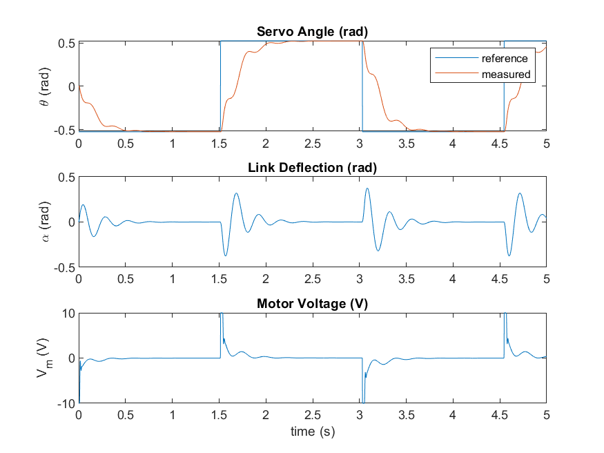
As shown, the controller tracks the servo square wave setpoint, i.e., the desired position, and mitigates the vibration of the link, meeting our control goals.
Running the Control on the Quanser Virtual Rotary Flexible Link
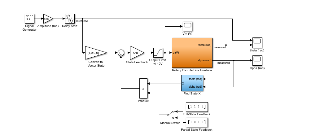
The LQR controller is ran on the QLabs Virtual Rotary Flexible Link first. The virtual twin of the flexible link system includes a more representative model of the hardware as opposed to the standard linear simulation used previously. The Simulink model used to implement the state-feedback control on the QLabs Virtual Rotary Flexible Link is shown below.
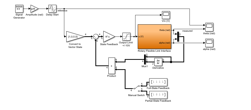
The closed-loop control response on the virtual twin is like the results on the earlier linear simulation. However, due to the noise in the strain gage measurement in the virtual system the control signal now has high-frequency components.
The first 3 cycles show the response when partial state-feedback control is used, i.e., when the Manual Switch in the Simulink model above is set to the downward position. In this mode, only the states of the servo are used, and the controller becomes:
![]()
This is effectively only doing PD servo position control and does not consider the link angle.
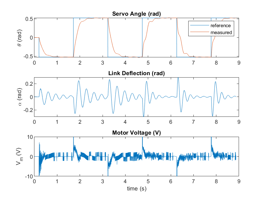
The last 3 cycles of the response is with the full-state feedback control that takes into account the deflection of the beam and tries to minimize it.
![]()
In full-state feedback mode, the oscillations in the flexible link when the servo changes position are dampened.
See the video of the virtual twin in action here.
Running the Control on the Quanser Rotary Flexible Link Hardware
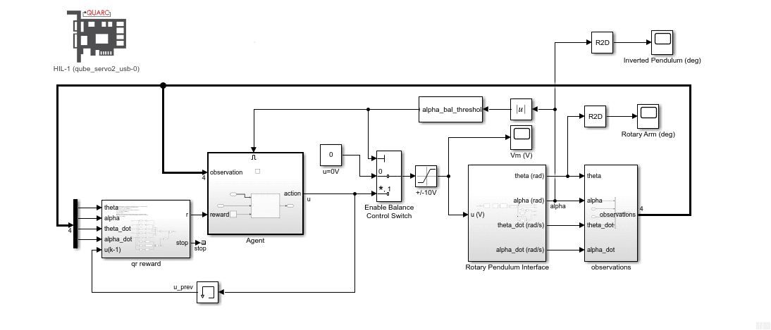
The LQR state-feedback controller is ran on the Quanser Rotary Servo hardware using the QUARC Real-Time Control Software with the following Simulink model.
Due to the inherent noise in the strain gage, the position and velocity of the flexible link angle measurement are filtered. A sample closed-loop response when running the controller on the hardware is shown below.
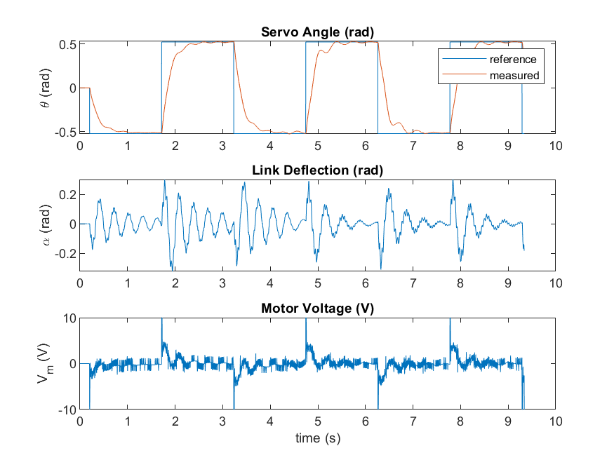
Similarly, to the virtual twin, the first 3 cycles are when partial-state feedback control is used, and the last 3 cycles is full-state feedback. Compared to the virtual twin response, there is more noise in the hardware. While the Virtual Rotary Flexible Link does have sensor noise, it does not match the same noise profile as the actual strain gage used. In addition, there are disturbances (e.g., strain gage cable) that are not captured in the virtual twin.
See the video of the hardware in action here.
Final Remarks
The full state-feedback control reaches the objectives set of controlling the servo angle to a desired command while minimizing the vibrations in the flexible link. The System Identification Toolbox yields a very accurate model that can be used to design a successful controller and saves a lot of development time.